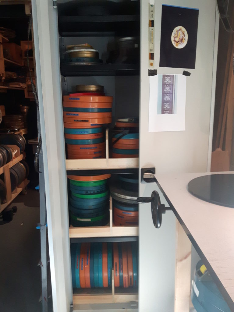
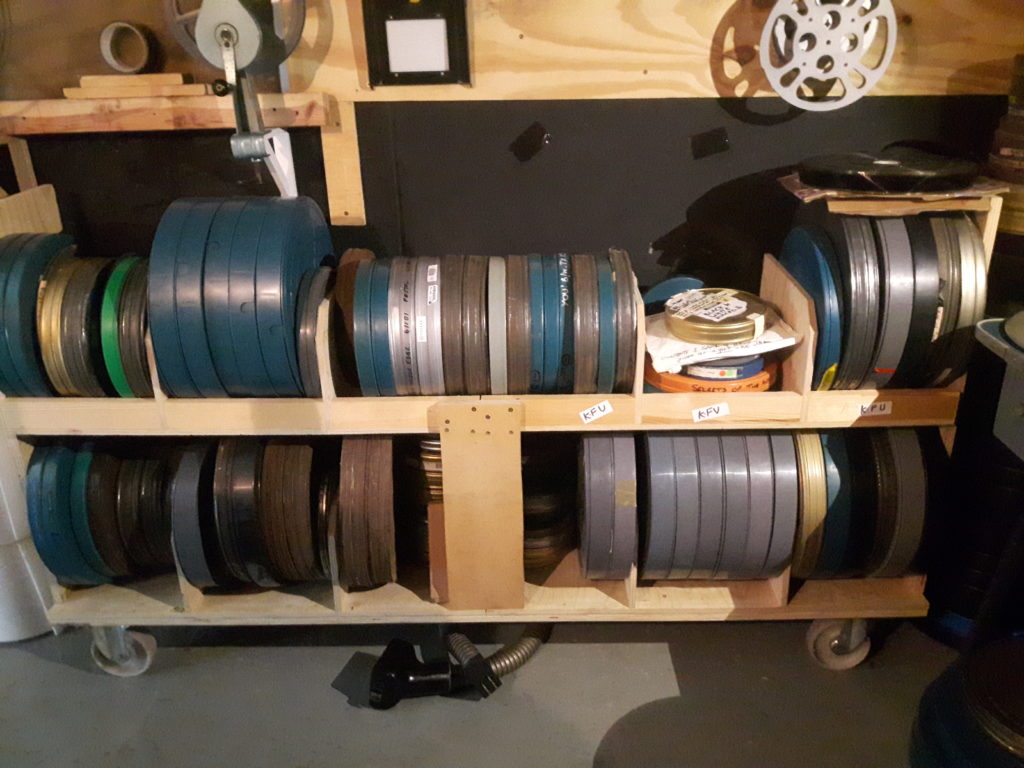
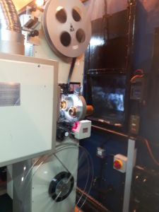
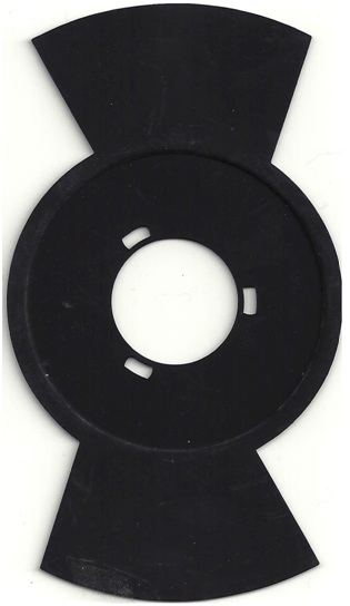
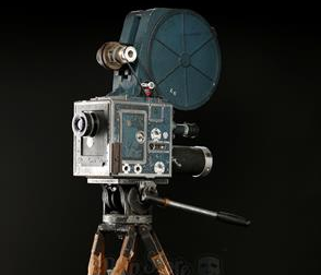
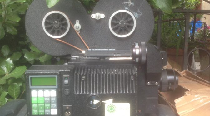
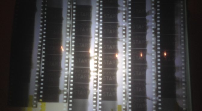
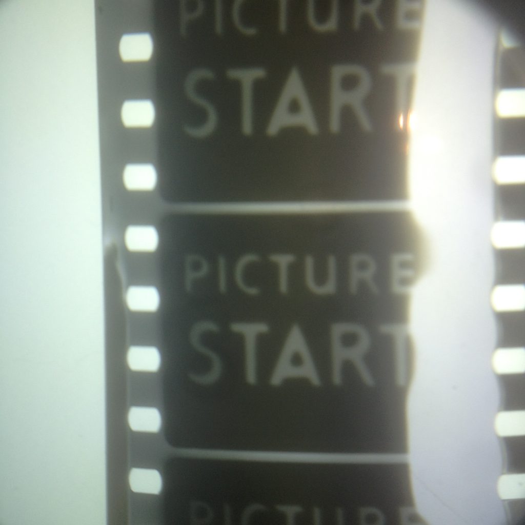
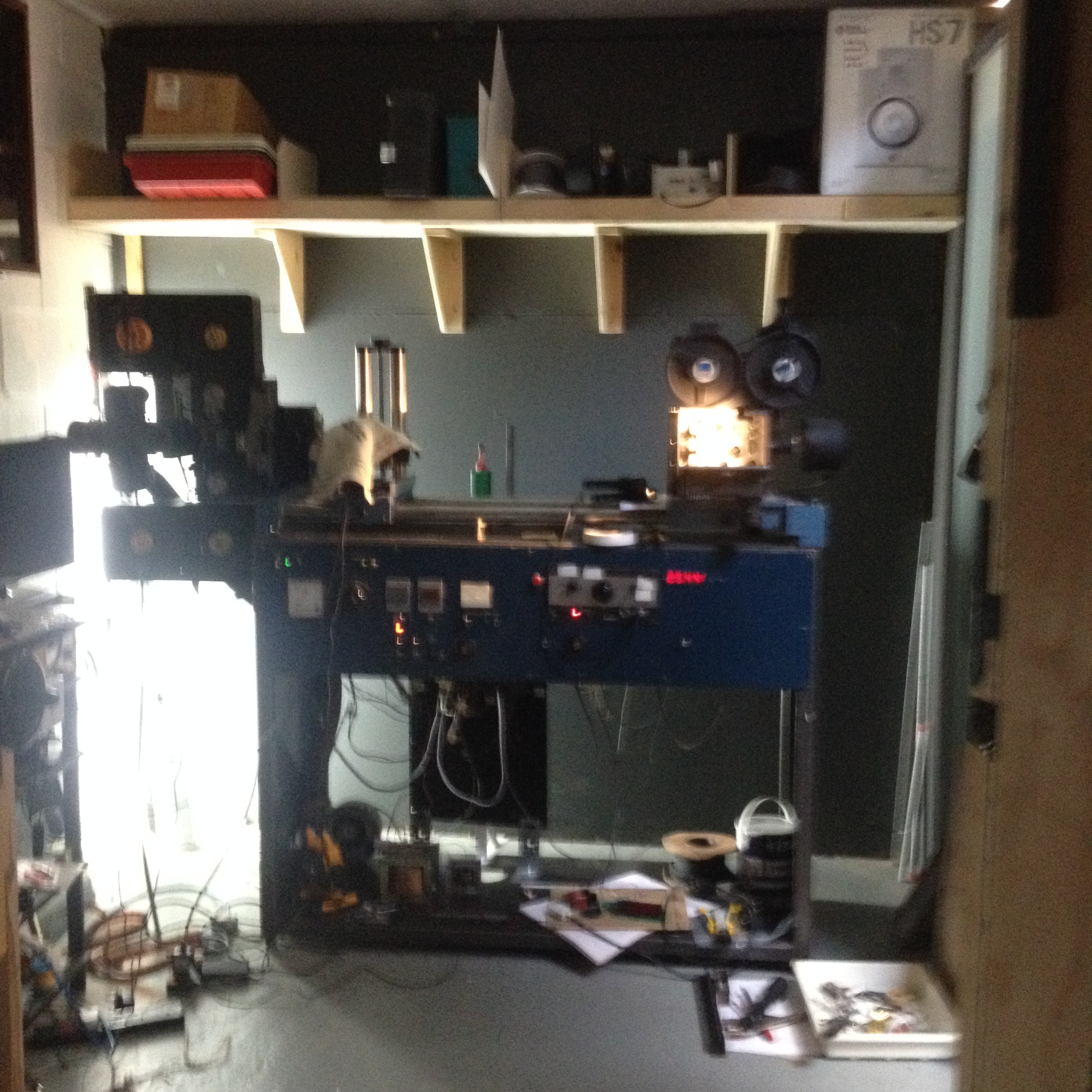
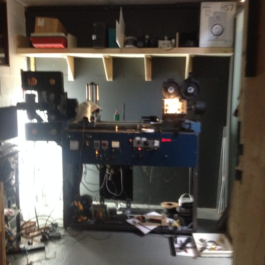
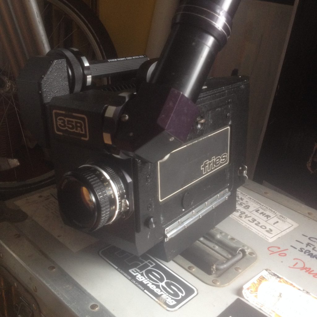
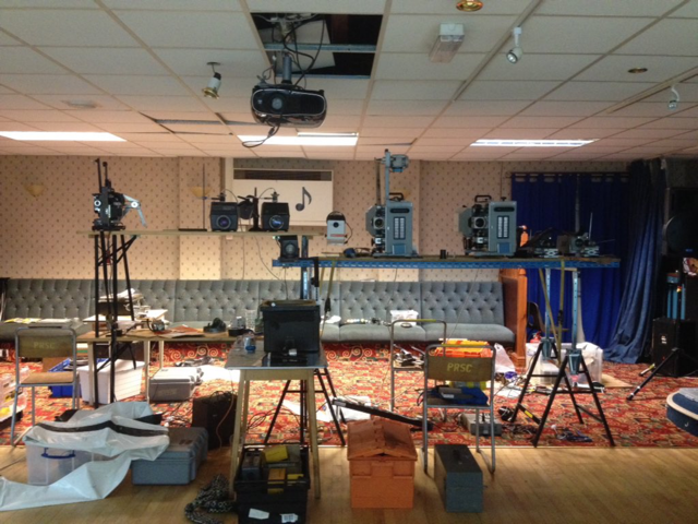
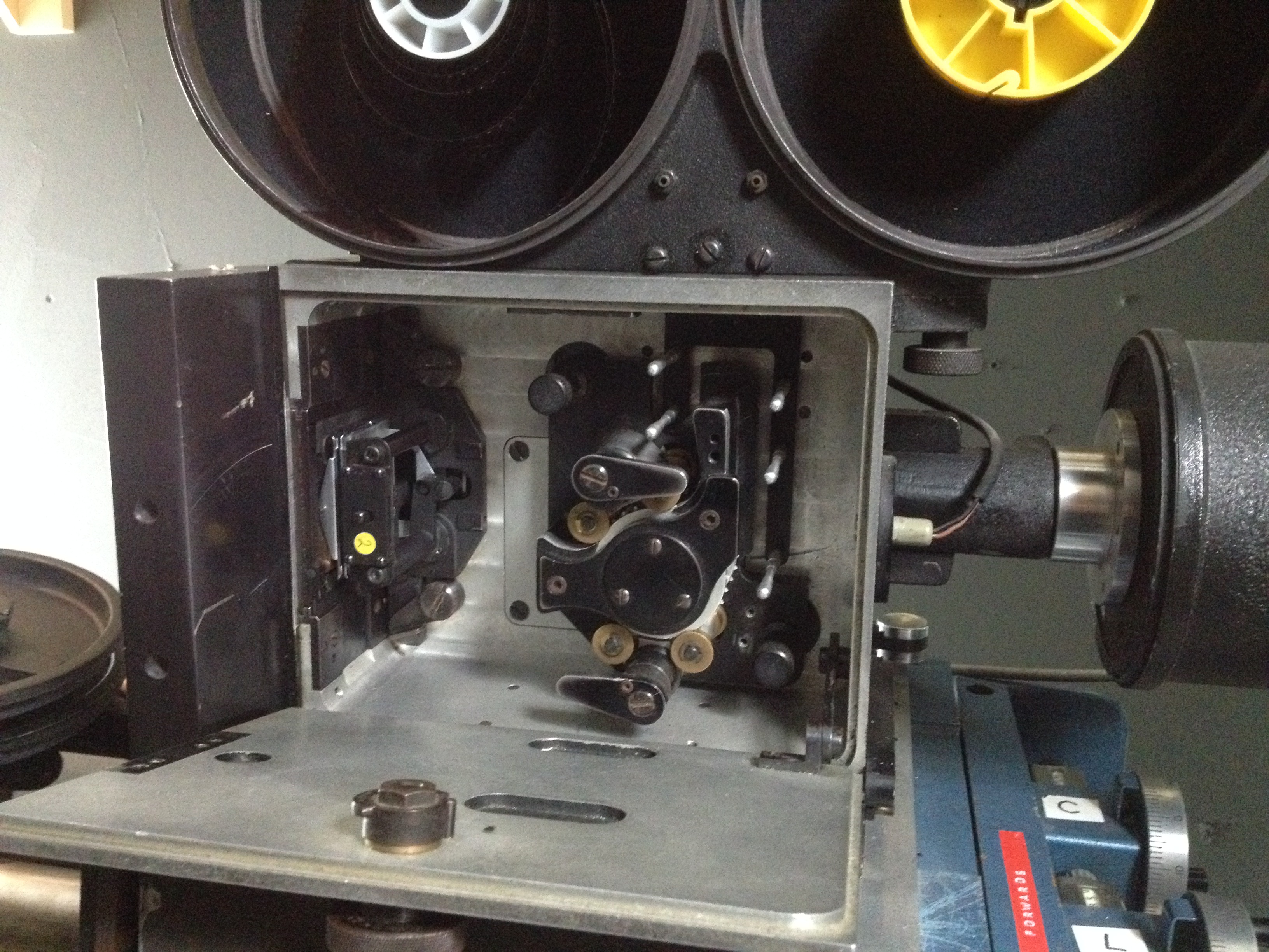
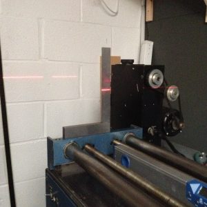
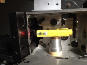
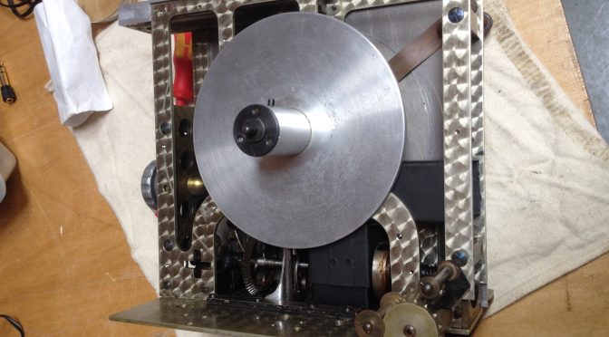
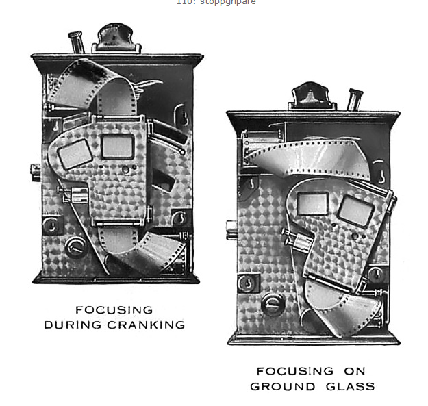
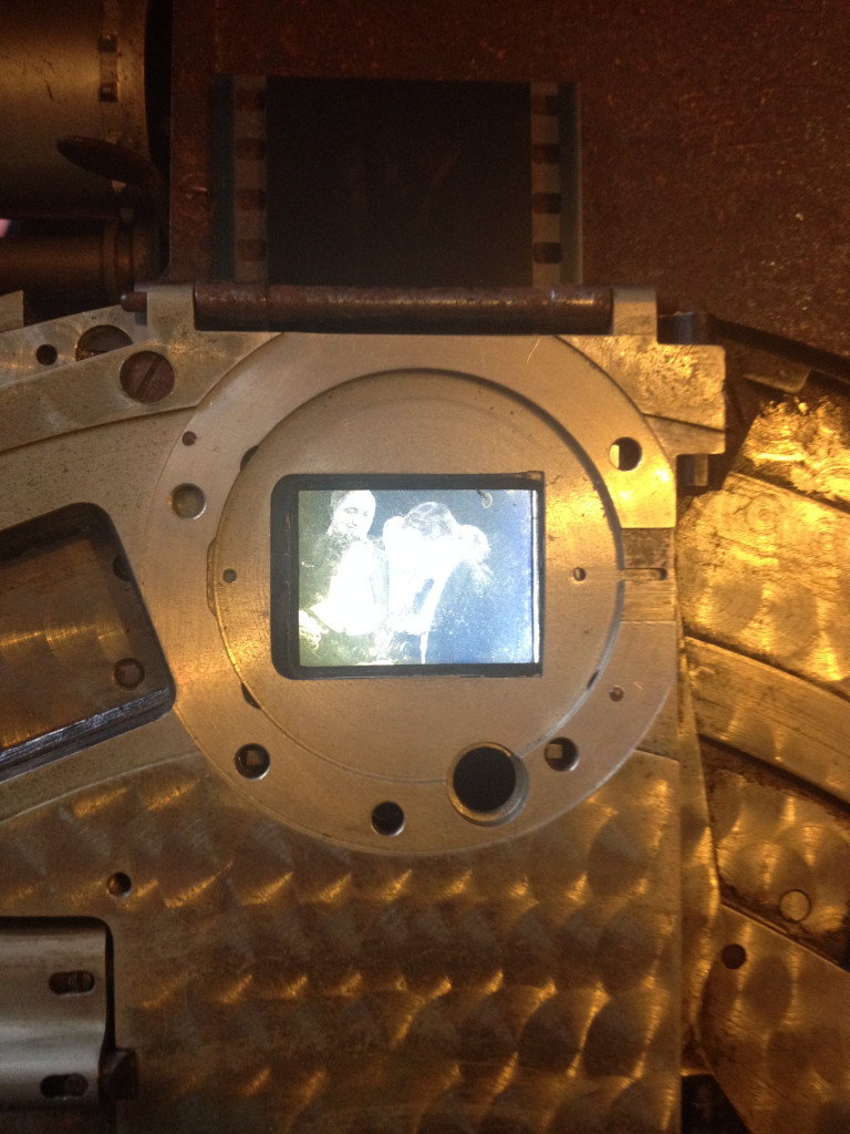
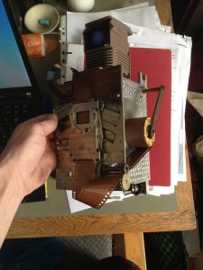
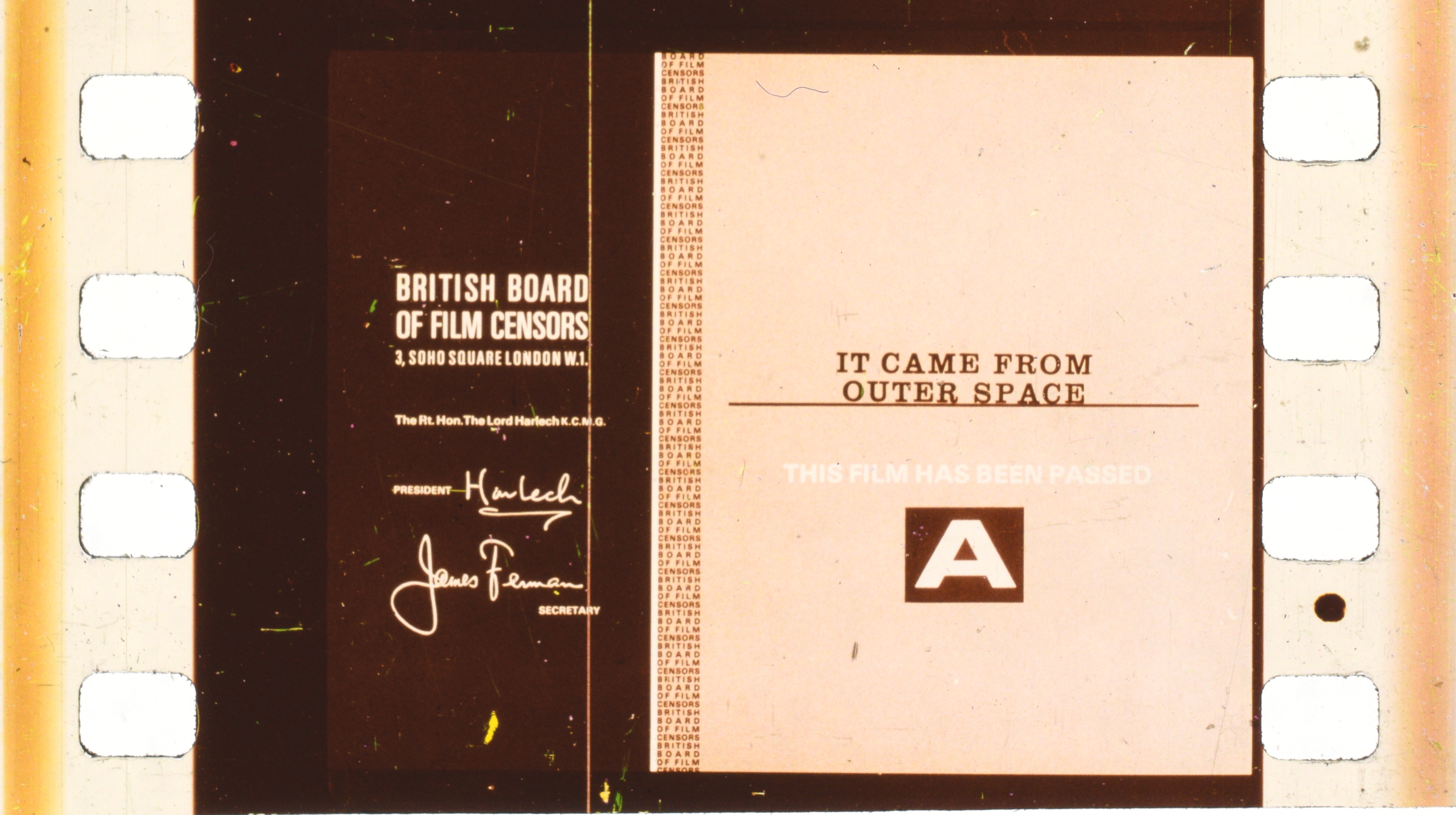
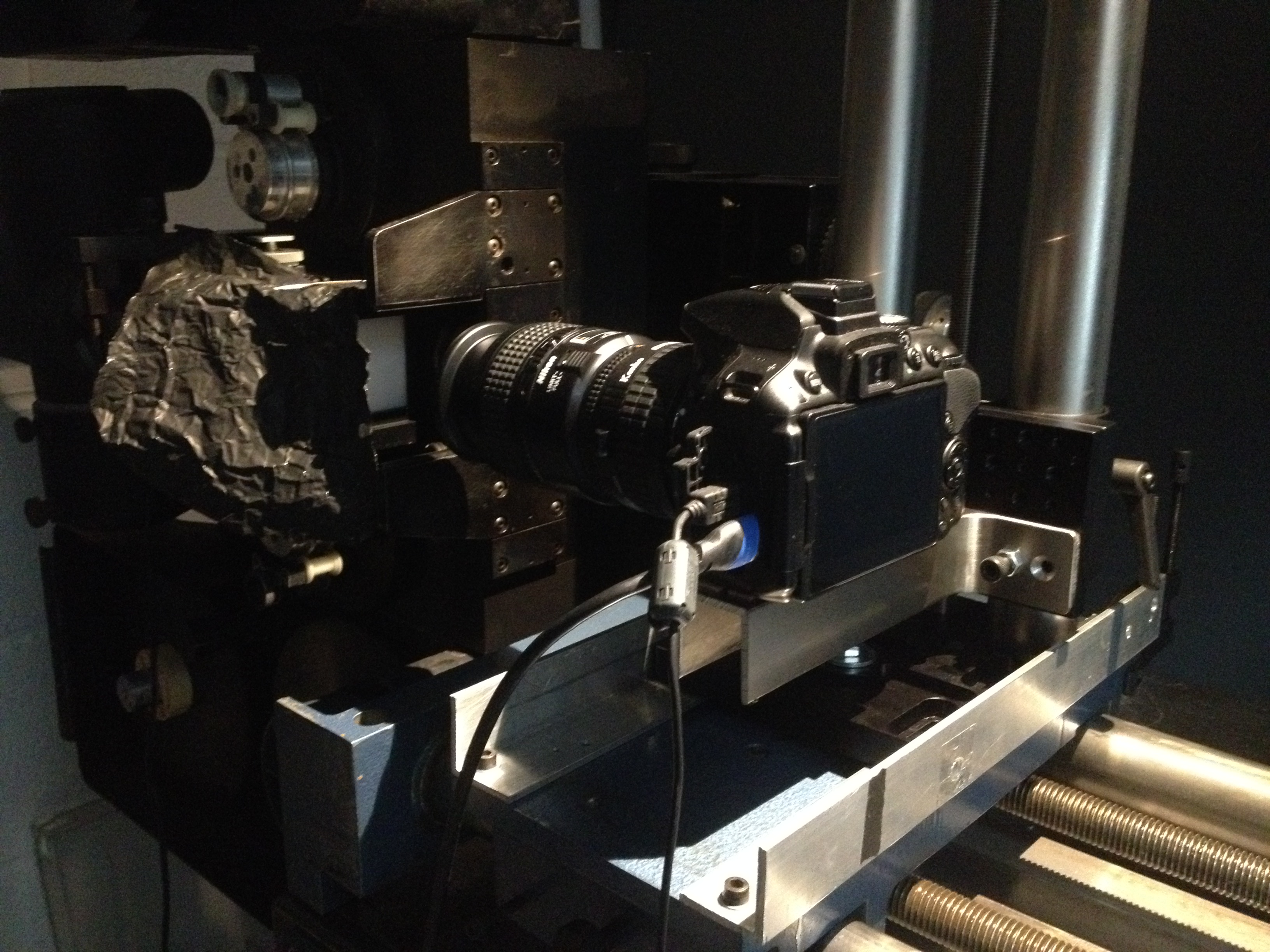
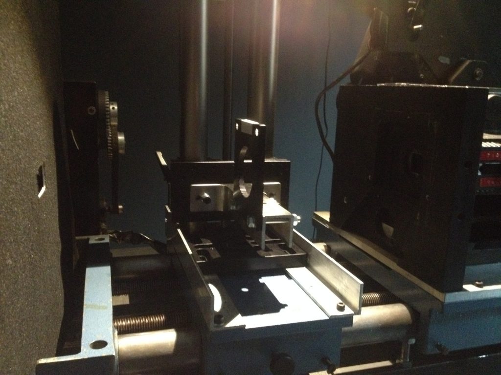
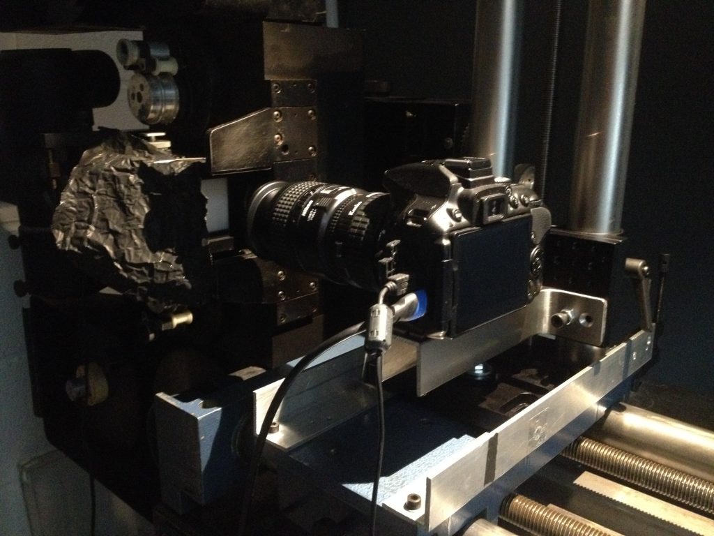
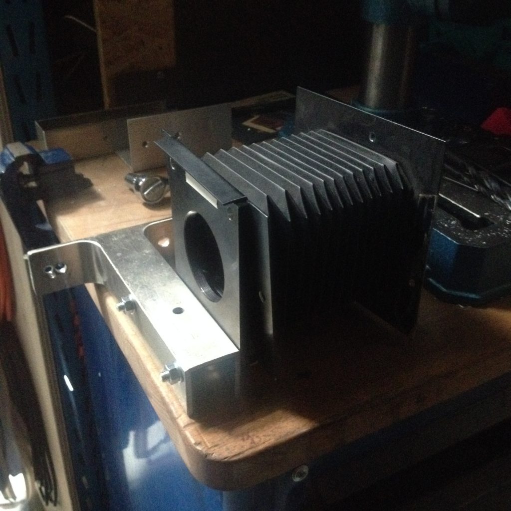
Heres a page or more on those great 35mm so called portable projectors you come across when you go to north Finland to teach how to fix 16mm projectors and someone opens a cupboard and there is two of them sat there waiting for some film love!!!
I got my first one, a Halogen lamp model from Ray Luton at the Watershed in Bristol. Then after my mate Rod had modified it to death, he graciously gave me a replacement, one of two Xenon models he’d sourced from the EAFA in Norwich.
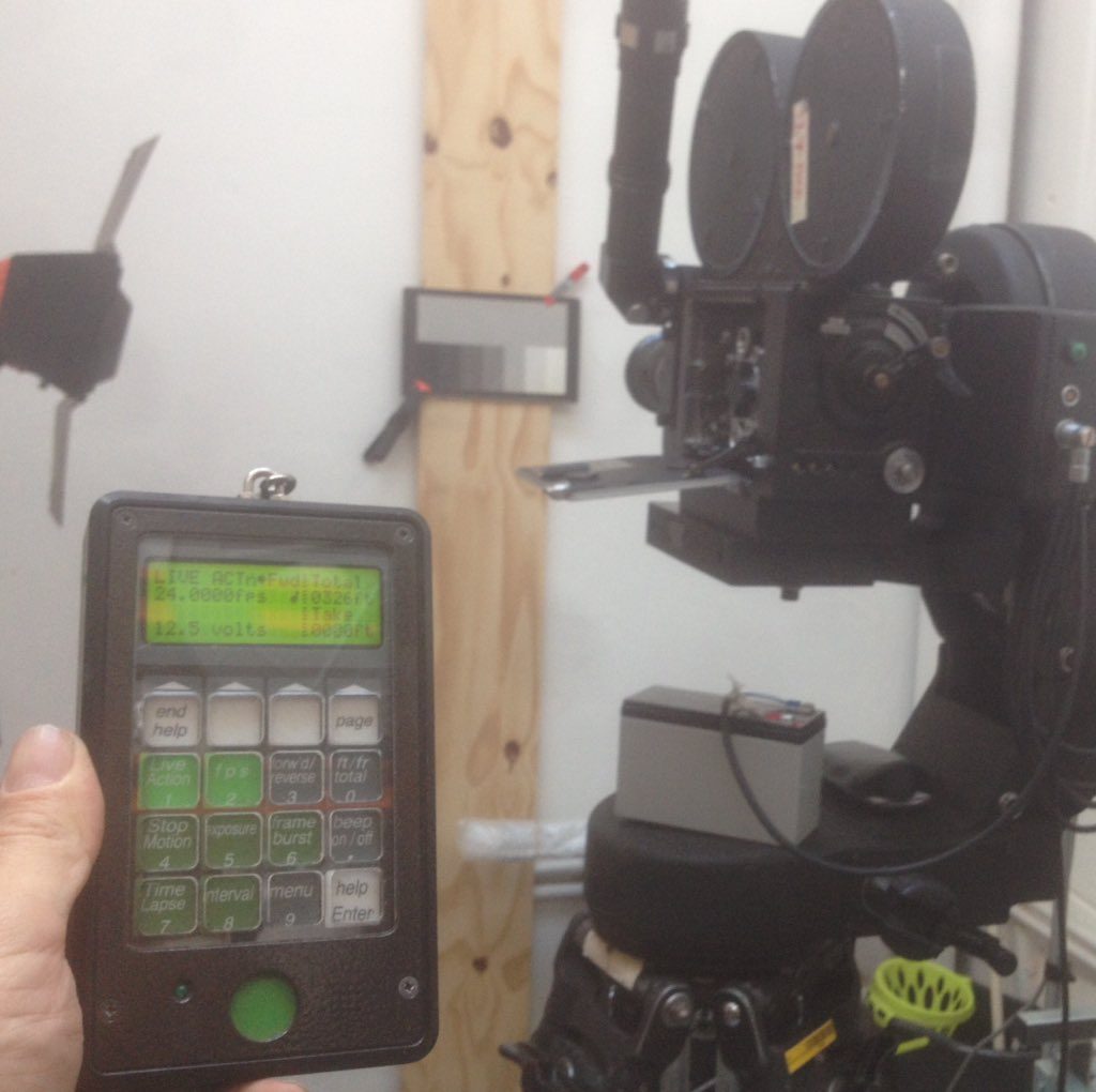
This is it in action. It has a mad modification that allows any frame rate from 3 to 30 FPS to one decimal point, so you could run it at 23.9 fps if you were so inclined. Of course, there is no hard 24 setting, so when you do want to run at 24, it invariably goes to 24.3, or 23.8 etc. Oh well.
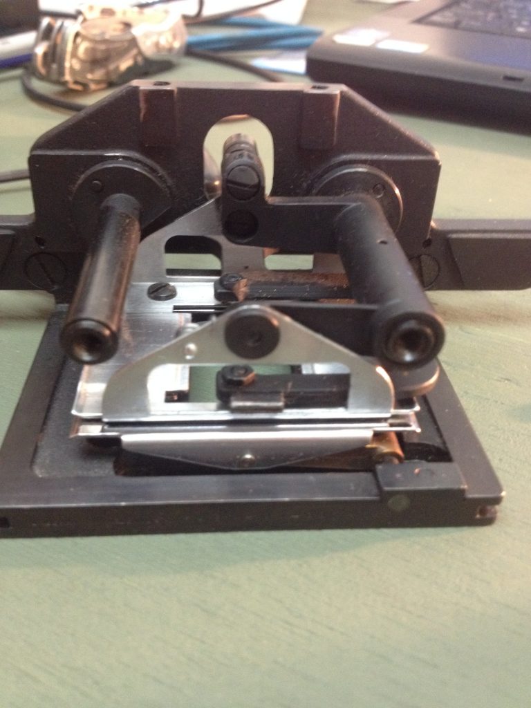
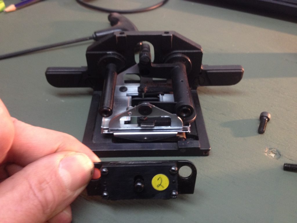
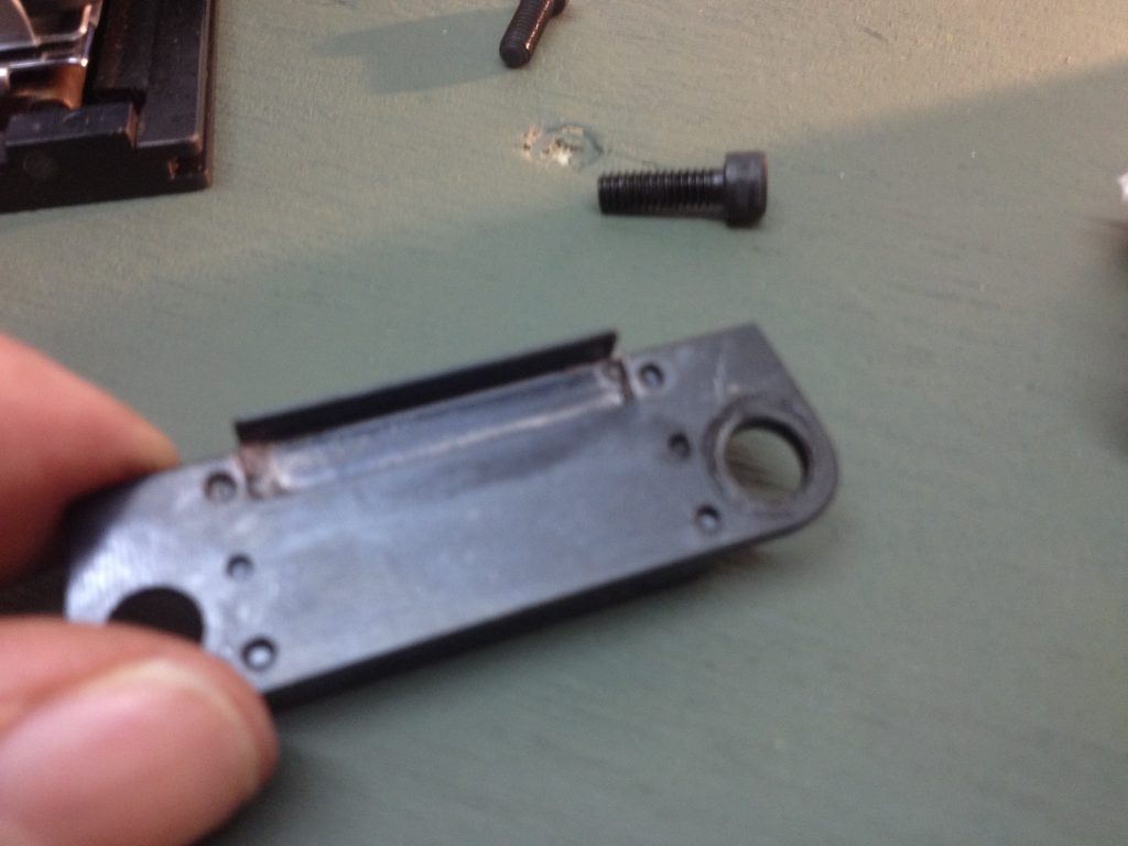
Anyways, they are nice machines with a fairly open film path that’s not too hard to lace up. Ill put details of lamps here, both Xenon and Halogen. Also minor fixes like the rubber O-ring replacements and perhaps details on the aperture plates which I had made for me.
They are not ‘portable’ unless you are a 10ft Gorilla. (Joe Young??) It takes two people to lift them.
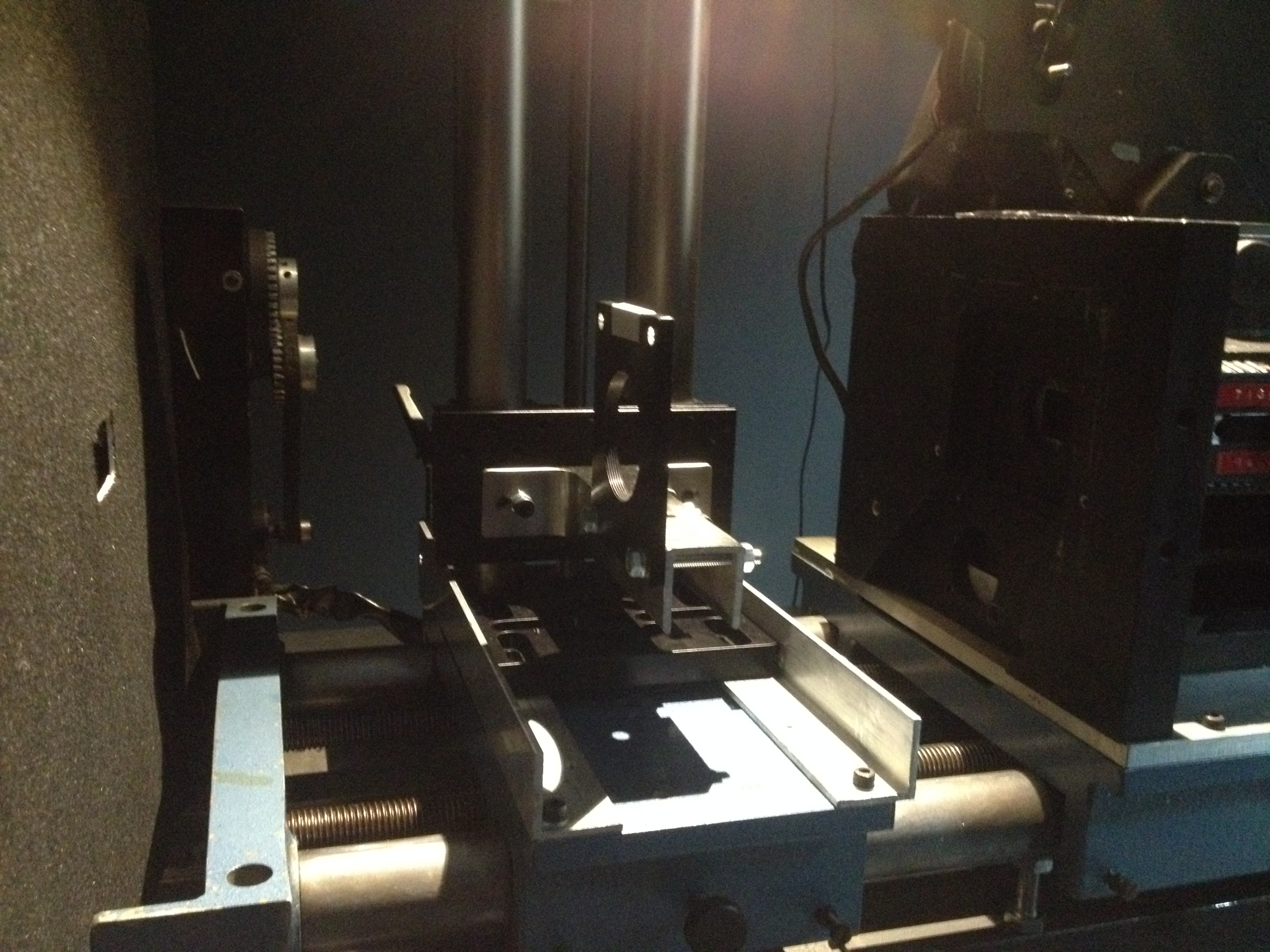
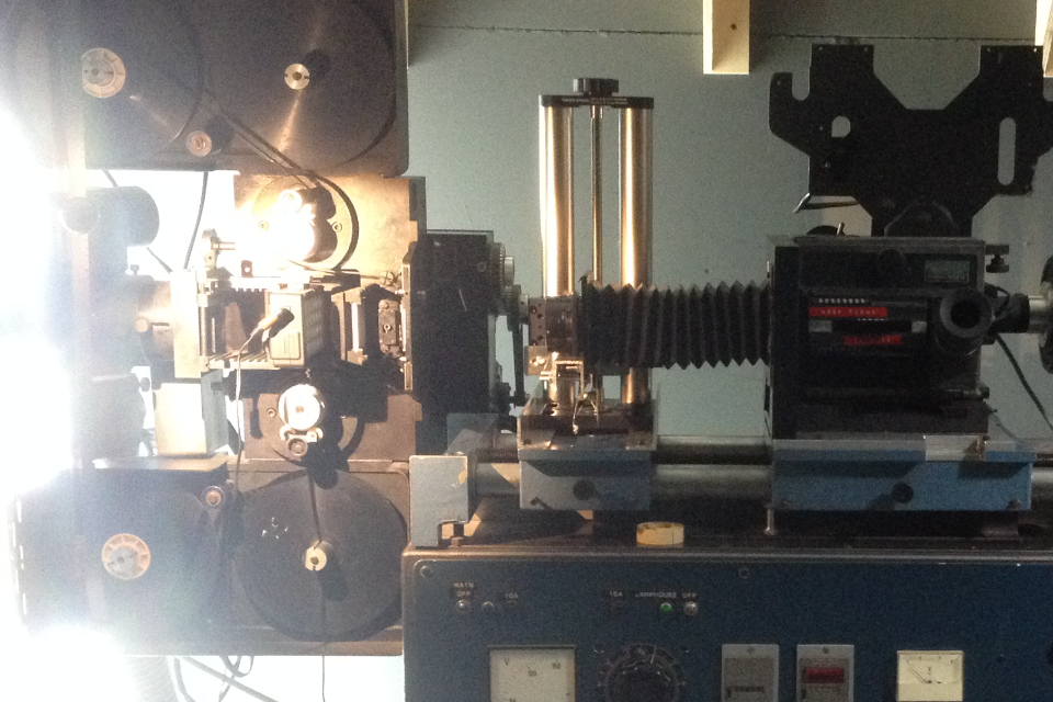
The Xenon models have a significantly larger lamp house and look more bulky.
‘Migno’ in Italian means ‘Little’. I like the play on XenON, by adding an N to make MIGNON, I guess meaning ‘LITLLE XENON’.
They were manufactured by Microcine. But cant find much online about this company.
Heres link to nicely made video showing one in use.
One thing about these projectors as you can see from this clip is how far back the lens is seated on the main body. Of course there is room for a scope adapter, which are very large compared to 16mm ones. But this distance, as Rod always tells me, precludes wide angle lenses. Ill do some tests and come up with a focal length but for use in a gallery (or anywhere for that matter) , you cant use wide angle lenses as they hit the side of the machine. Shame.
The reel spindles are 7mm I believe and you can fit large capacity reels on the large spider reel holder thing that clamps on top and has an electric take-up motor.
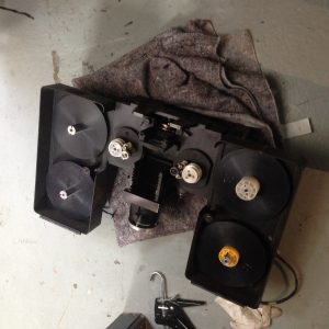
Here’s my old Halogen one. I cant remember what lamps it took but the ones in Finland take vertical bi-pin 300/400 watt lamps and use a mirror. In many ways Halogen models are easier to use. 1. Theres no paranoia over striking the lamp. 2. Theres no obsessive hour meter reading. 3. MUCH cheaper to have spares. 4. MUCH easier to replace. 5. There’s no fear of lamp blowing up!
Yes, a Xenon lamp has a brilliant colour spectrum and are very bright, so the best for really critical, cinema style screenings. But lamps are NOT cheap. (Ushio/Osram)
You can see the difference in the lamp house in these pictures above.
Mine only has a mono-sum balanced audio output. I guess you could fit a stereo reader and wire up a Dolby CP650, which you see around cheap nowadays, or even a CP55 which are even cheaper and easier to configure and you can get new CAT150 cards (see Dolby Legacy services) for. But while I’m here did I tell you about my crazy multi-channel sound from mono idea? You take the full range mono signal and split/matrix it into 4 channels. The you make extreme EQ adjustments to each channel/speaker to favour the programme material. Ie, channel 2 (Centre) you EQ the hell out of for dialogue. Channel 1 and 3, you EQ for music. Channel 4, roll off everything 150hz and above, basically a low-pass filter for BASS fx and noises/sounds. Will it work? Probably not, oh well.
Anyways, As there were two of them at Filmverkstaden I thought it would be nice to use them as a pair, side by side. So, as 35mm 2383 could be processed in Lomos I thought all we need is some way to capture onto the film, from projected material on super 8mm and 16mm. These would ideally be colour neg, to make a positive but they could also be b/w neg and via colour filters can do all kinds of composite things. The 35mm full gate frame will contain about 16 x super 8 frames for instance, or about 6 x 16mm frames. Could be FUN!!!
Contact print of work by Vicky Smith. (On left is b/w contact print from original on right)
Clip from found footage work that I am using a lot at the moment. A film about the British writer Somerset Maugham where he utters the line to the interviewer at one point “I draw the line at incest”.
I’ve been buying up as many kodak gelatin CC filters as possible with odds and sods of colours for a while now but the other week I bought a lot on ebay that seemed to have quite a few. When I opened them I was amazed as there is a complete set.
These filters are very useful when colour printing as this is going to be a focus going into autumn and winter.
As it goes, Kodak have ONLY JUST removed the listings for these filters form their motion picture products catalogue where they were listed for about $60 EACH!! There are 6 grades in each of 7 colours making 42 filters amounting to $2500 worth of gelatin.
One thing required for sure is longer and more complex tests. As the ECP process is not quick, its important to yield as much info as possible from runs through the printers.
Heres a bit of fun with LEE filter number 242, a kind of pale green meant to balance flourescent lights out but here placed over a magenta faded film strip. As the Cyan and Yellow (=green) layers are the ones that have faded the LACK of green makes the image that ghoulish, ghastly, sickly, pink colour that is so common on old film. Its not perfect, but now with a full set of CC filters I can tweak this test until it works.
Optical printers are traditionally slow to operate. Being devices that require careful setting up. The keeping track of many moving parts simultaneously results in a reputation as an arduous process. However I approach them differently. I think of them as a camera. An animation camera yes, so single frames are the shooting mode, but, as I recently discovered you can get work made quickly as long as you free up the thought that goes into what you are doing.
As there is a frame by frame metric afforded by the seperation of projector gate/film and camera gate you can think more of the sequence you are shooting as made of building blocks where each block is a frame. 24 shots of the same frame will be a second of a frozen frame. If you cap the lens for 3 frames, you will get a dark spot*, if you cap it for 1 frame between shooting that same frame again this time for 48 frames you will get 2 seconds of flickering image/black, the fastest flicker possible on film running at 24fps.
On/off, On/off, on/off, on/off, etc.
*of course you will get a bright spot in the OP print itself because no light reaches the film and it devleops clear. BUT, all this is being done knowing that after the OP print is developed, it will be contact printed.
If you now cap the lens for BETWEEN 1 frame and 4, 5 or 6 frames, just making it up as you go along, and also do the same for the frame, ie sometimes shooting it once, sometimes 4 times, sometimes, 3 or 6, then you will get a flicker that stutters and varies, it can seem almost musical.
You will soon rack up a master camera frame count.
Now, if that frame in the gate is number 1 (you can accurately number frames in a sequence by previewing and making note of their numbers) you can now goto a different frame, say 13 and then shoot in the same manner as above. You can pause, goto a random frame in your sequence, and shoot in above manner. You can shoot some frames only once deliberately, you can run others for seconds, hold off on flicker, bring flicker back in…..etc. That frame count is going up, you will soon get to 1000 frames, 25ft, which is a good length of material for somekind of expanded cinema performance.
This is all exactly what I did with these loops (video above) where you see them side by side, then overlayed. In total it took a day. Including the contact printing.
After I’d made it to about 25ft I processed the optical print and then contact printed it. I then selected a very short length of them both, exactly the same bit in neg and pos and laced the loops into projectors set for 18fps.
The original material that was in the optical printer projector gate was black film that had been melted in my friend Manivelle. I melted a length of film, not every frame and also I used both sides, emulsion and base. I melted some heavily and some only just get burnt. The film is black print film that has no image. The melting and heat have the effect of making the image. Many kinds of image are made this way, infact, they are like fingerprints or snowflakes, every one seems different. The heat of the lamp in the Eiki projector, the good old halogen xenophot 250w-24VDC is the agency of the heat and focus and thus the cause of the melting and thus the author of the image. Each image is a tiny moment of thermodynamics and plastic in a state of rapid destruction. All films burn differently. Old black and white films leave a brown dis-colouration, some colour films hardly melt at all, then burst into a pyschedelic nebula of bubbling chaos. But for now, im just exploring pure melted-film on black imageless film.
Manivelle is of course a performance Eiki. She allows close contact between the frame in time and the sequence in memory. The motor having been removed forces a new relationship between the film strip as slide show and the rapid slide presentation of film as moving image. Manivelle also allows a precise backwards motion! The melting film, when it is allowed to happen is a real occurance. It happens outside of frame rate or resolution. So these above experiments are a further exploration of live melted images, their forms now recycled as ‘representative’, ‘illusions’ possibly OF something that was real, once.
So just as you can (and many people do) use a Bolex in single frame mode, counting, rhyming, triggering, thinking in ones, repeating, you can also do the same with the optical printer, the only difference is that you have a pre- selected array of images to put in the gate.Or perhaps you haven’t thought about this at all and have grabbed a load of random clips. Maybe you are printing loads of random b/w clips to colour (like 3383) using another random pallette of coloured gels!!
If you wanted to pre-plan a precise, musicalish score, you could write all the counting down on a chart with a column for projector and column for camera, thinking and devising in a more comfortable and relaxing space. Then coming into the territory of the OXBERRY and thrashing it out!! Its not optical printer that are slow, its the way that we use them.
I had the enormous pleasure of running two workshops recently at the amazing lab space filmverkstaden in Vaasa, Finland.
Such a great bunch of people came and it was really nice to do a hands on, practical workshop where a high degree of usefulness transpired.
Even though I have serviced and fixed many Eikis in my time I’ts still kind of fun to deal with common machine problems like deeply hidden lubrication to free stuck or jammed parts.
Its made me think that now is a good time to make a full documentation of how to go about looking after these machines (the service manual is a good place to start people!) and how to deal with common issues and problems.
4 TYPES of LUBRICANT: Engine (Petroleum) oil. Silicon oil 100cst. Silicon grease and Molybdenum disulphide grease.
As well as these I find one other thing useful in some situations. Aerosol 3in1 oil. This is useful for 2 common issues, the sound drum guide wheel getting stuck and the retainer spring pins that locate the take up and pay-off reel arms. When these become stuck and dont move freely a little 3in1 spray, aimed into the mechanism can free them up without the need to disassemble parts which in the case of the guide wheel is tricky.
These 4 types of lubricant have particular jobs which I have summarised generally in this chart.
But the service manuals, pages 20 – 25 has a comprehensive list of parts and their corresponding lubricant.
Here we see the switch from petroleum oil on worm/fibre gear to grease for later SSL models. Possibly Oil was a typo? as it is runny it will quickly leave these connecting gears and drip inside the machine. I’ve always used Silicon grease.
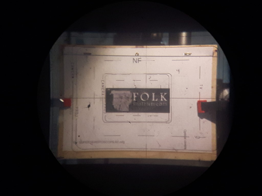
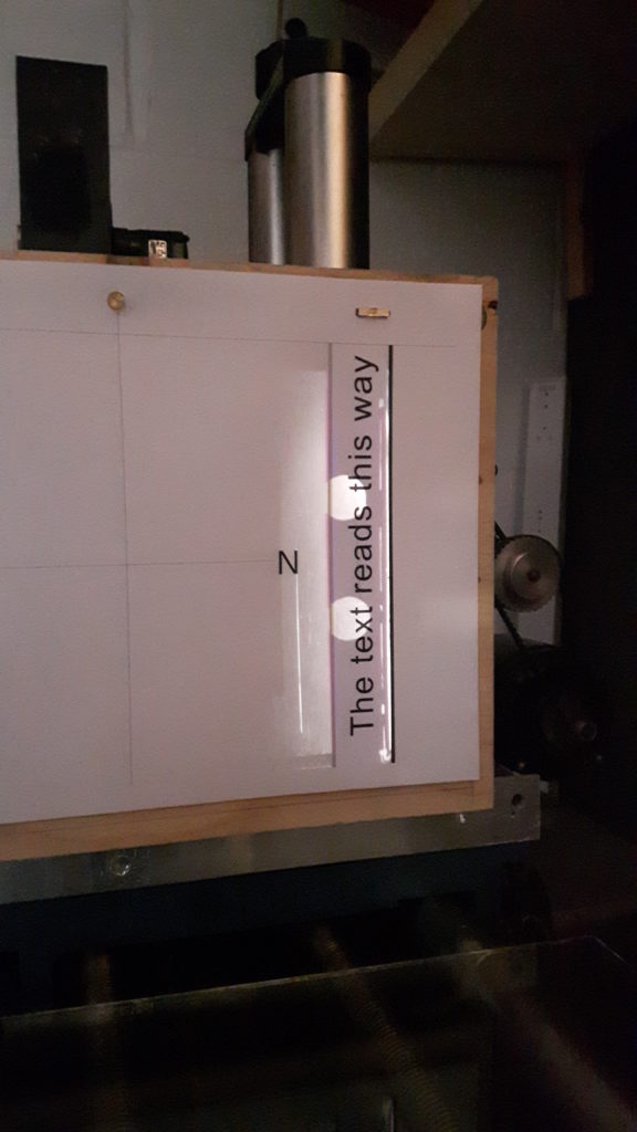
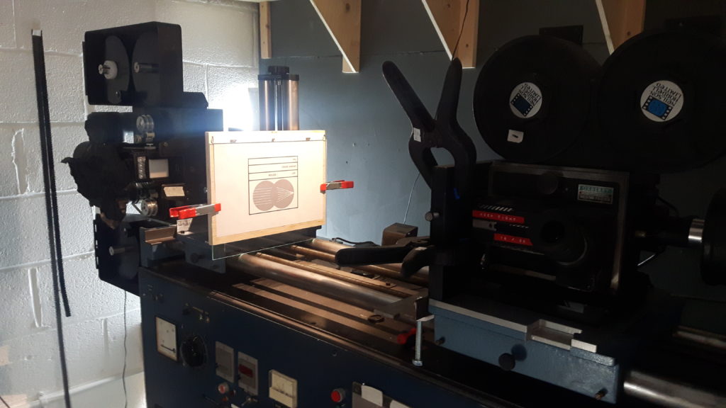
Heres the white card test showing how to hold it over the gate and then the view through the view finder that shows the image in the gate and how its edge lines relate to the reticle guide lines which are typically hard to see because the black surround renders them impossible to see. The vertical card visualises the horizontal top/bottom guide lines and the horizontal card visualises left/right guide lines. Sounds confusing perhaps, but in practice its super intuitive and makes complete and utter sense in way that makes you say “oh my god thats so easy, I wish I’d thought of that”. And I say you did think of that because this is me talking to myself in some stupid banal commentary on something no one looks at let alone reads…..
Set up for upcoming VI / motorhand / expanded noise projector dissassembly / projector as CV and signal source / apparatus / melting-burning shows – North Europe Tour 2026!!
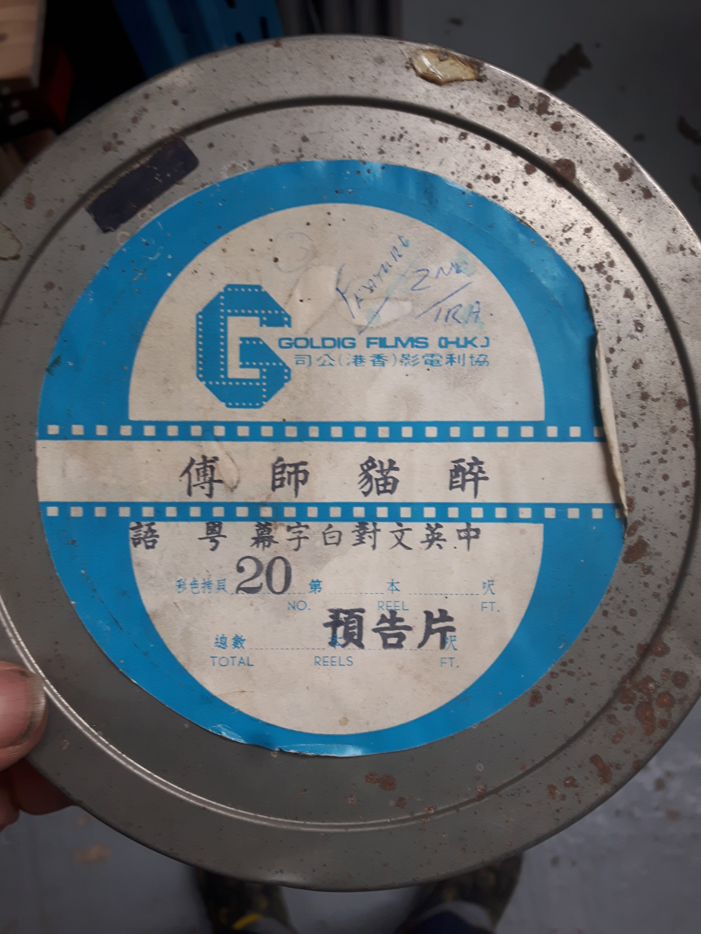
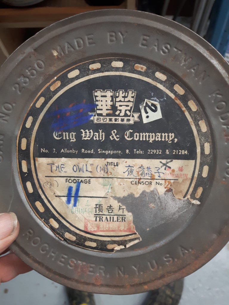
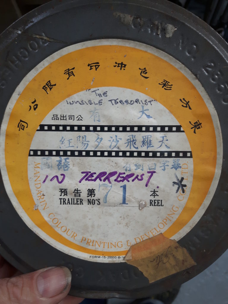
Ive been making some internegatives or intermediates on 35mm 2234.Copying from found cinema trailer material.
The colour will be lost of course, as will the sound, but it is going to end up on 16mm with mutiple exposed layers, so its not that a loss. The marks on the original tell me which frame to compare, the actual sequence is only a second long. This ineg is shot at ND0, so close comparing of the target frame and neg is necessary to see which setting has best tonal range for what Im trying to do, which is focus on bits of fire in the clip. When double or more exposing it to print stock I will stop down ND1 for each layer.
Next up similar treatment but on colour 16mm print that I want to preserve, ie not destroy in lliivvee performances , so necessary to copy via blow-up to 35mm and then print back down to 16.
Being able to make a negative from original positive material in order to be able to print it again in different ways or combine with other material or transform it in other ways is very useful. The Kodak 2234 stock is a low contrast, low speed, fine grain stock that produces what look like ‘thin’ negatives. It is processed in D96 same as many other stocks.
Learn know how to copy positive 16mm material (reversal/slides/found footage) to 35mm interneg, then print back down to 16mm print stock.
HOW:
This is possible using an optical printer. Although the operation is straight forwards there are many auxiliary creative things you can do like multi screen, step changes, exposure variations as well as the main aim which is ‘Can we get a positive as good as the original?‘ Using an intermediate kodak stock specially designed for this job we will be exploring both technical transfer of densities but also some of the things afforded to us by the geometric and dimensional variables on the printer.
WHO:
This is aimed at artists and film makers who are already working with 16mm and are looking to deepen the process understanding and explore what copying, duping and intermediate steps can allow.
B/W reversal film is popular and gaining popularity but ‘any’ reversal original (unless you digitise) has a limited life of use, projection, handling , etc being an artefactual and thus precious camera original. This is where intermediate steps come in. If you enlarge 16mm to 35mm you create a new copy/layer where creative choices multiply and widen. Printing 35mm back down to 16 means almost no quality is lost and you now have a whole new layer of control, keeping your originals in perfect nick!
WHERE:
Nachleben Lab, Rendlesham, Suffolk, IP122TW (yes, near site of UFO landing)
WHEN:
When enough people sign up. Limited to 4 people.
WHAT TO BRING:
Ideally bring some b/w positive original material in 16mm, either something you have shot and processed or some found footage. Single perf is preferred but double perf is possible. You dont have to bring this as there will be material here to choose from.
YOUTUBE. Love it or hate it? Well, I’ve decided to try and make more use of it to document in a more useful way the stuff I am doing. I’ve been uploading very short, basic video clips of various processes and small things that occur when I am working to try and populate the channel with material. In the future will hopefully be longer and better made/edited clips demo’ing the activities at my workshop.
Amazing illustrated talk by John Knoll at ILM about making mattes from colour elements. Hope they dont mind me posting link here as its worth saving somehow.
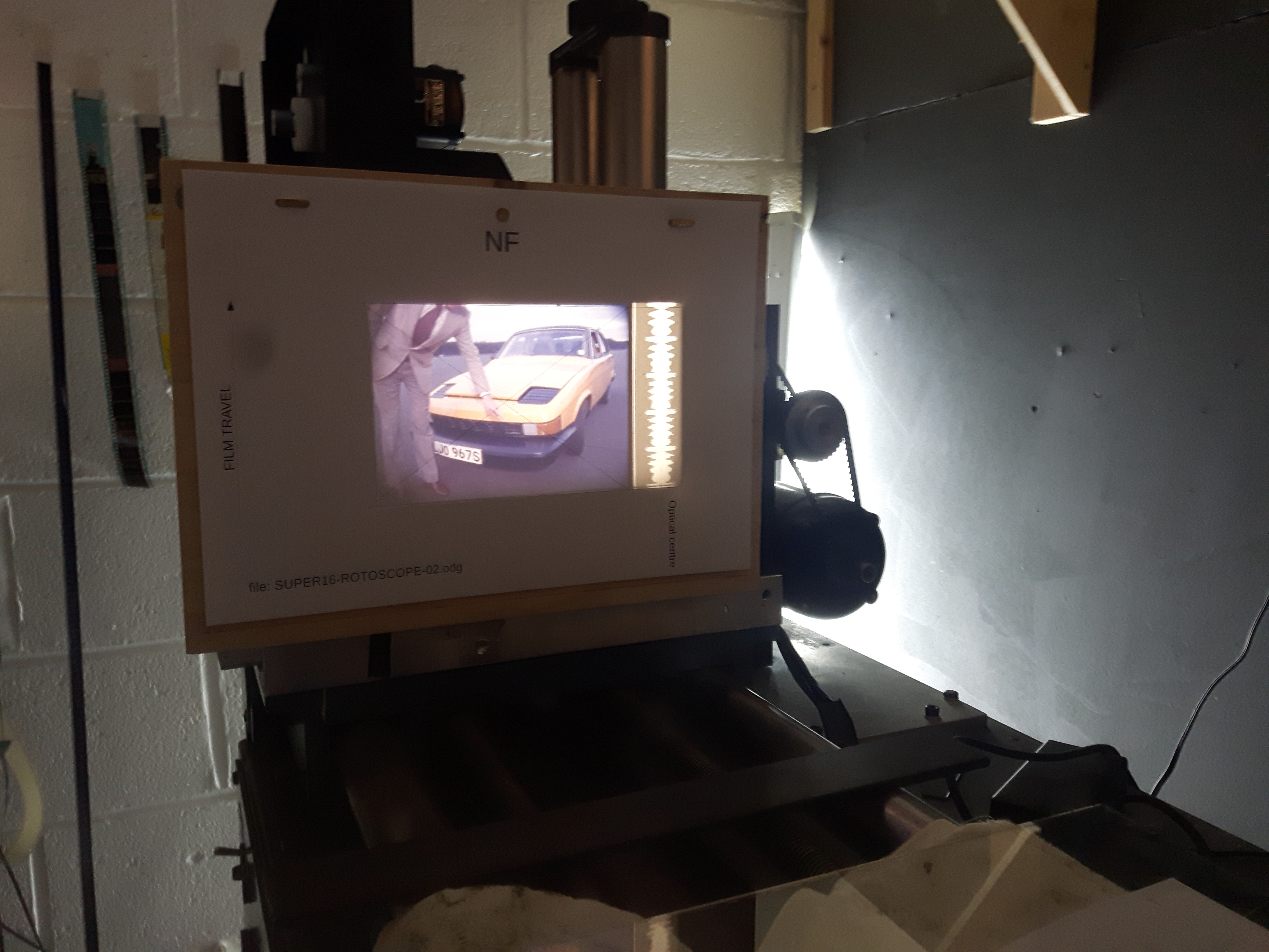
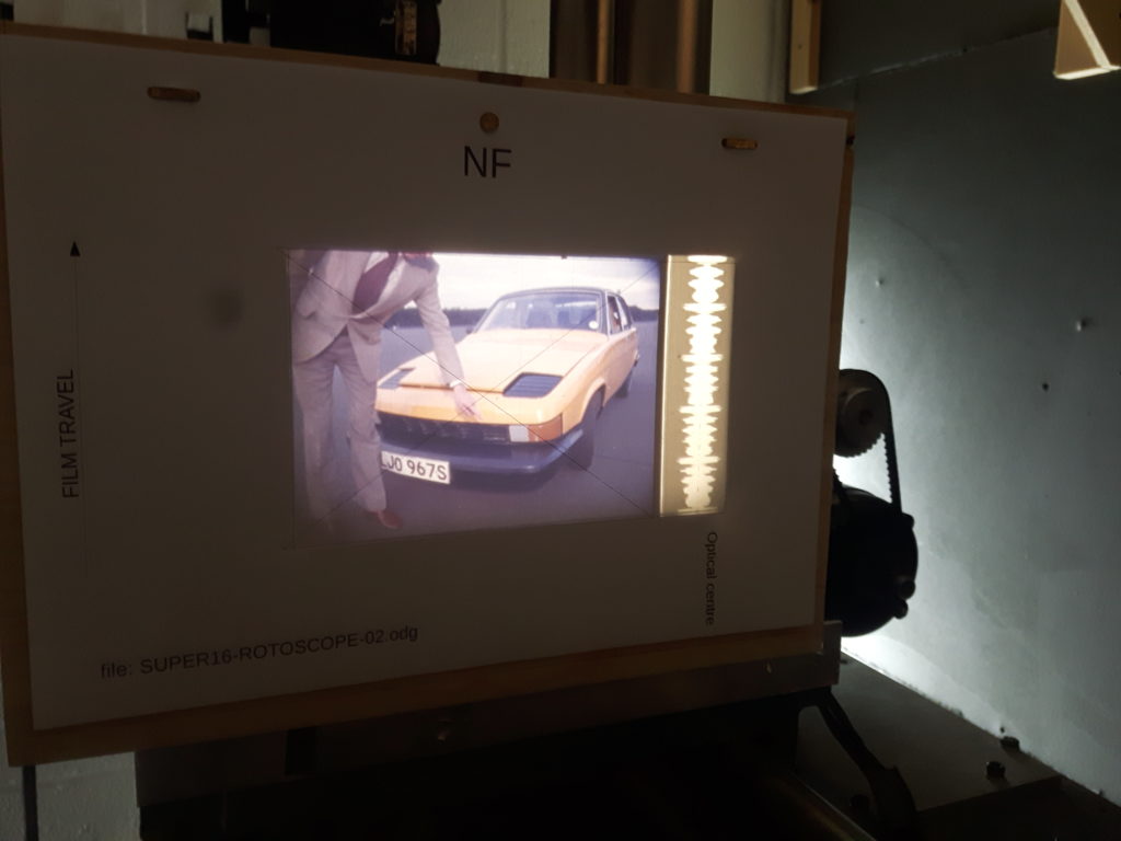
Quick document of rostrum/rotoscope camera set up.
This adapted Oxberry camera, (presumably from an old rostrum camera) has had a new stepper motor added which is under digital programme control. It uses a Nikon F lens mount and I’m shooting lots with a Micro Nikkor Nikon F 60mm 2.8 lens. It is DUAL gauge and I have gates and sprocket drives for 16 and 35mm.
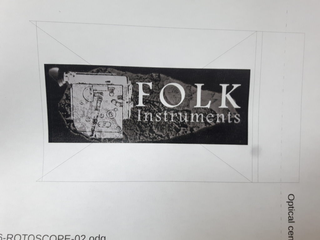
As it turn out 16mm uses an A4 punched paper and 35mm uses A3. In the days of rostrum film animation things were done in field sizes so Im currently working out the best way to achieve best setup for main field sizes in these formats. The barcode picture is for value 0 which will expose into the soundtrack area on 16mm and I’m trying to make some optical sound experiments using this way of generating sound from mumbers.
Chromacolour field sizes (https://www.chromacolour.co.uk/animation-supplies/dope-sheets-field-guides.html)
The artwork area can be lit with LED lights or two Arri 2K floods depending on what film you use or want to do. If other lenses are put on and the camera is moved back a large area becomes available to shoot.
The motor is very programmable, driven by a CL57T, run from an Arduino UNO.
You can shoot single frames and multiple frames by assigning a number to the button. You can enter a number manually to shoot. It opens to H mode or ‘half’ so you can rotoscope a piece of film in the gate, infact you must do this to focus. You can also have set time B mode for long exposures. It records frame numbers accurately and goes forwards and backwards. The speed is adjustable but I tend to run quick wedge test with light metered for the stock and see which F stop looks best. ((MUST ADD EMERGENCY STOP!!))
All in All I am super happy with this build, it is a very versatile tool for making images, esp from flat artwork and I cant wait to shoot some 3D stuff I have been collecting from around the wild areas where I live.
Early on in the formation of the DIY film lab scene there was a meeting in Hamburg or possibly Hannover (sector 16) or somewhere else where I saw mentioned the idea of converting steenbecks or other flat bed edting tables into contact printers. Esther also mentioned this at WORM and a howto appears in their DIY booklet. So I have always wanted to do this and now I have and it works very, very well I dont feel the need to get a contact printer. Also as it doubles up the use of one machine into two, its very economical.
The main thing is that everything is there to allow this BUT somekind of device or part needs to be built that creates a small slit which the light passes through as films which are bi-packed travel pass. We know from how ‘proper’ contact printers are designed that this slit is crucial in producing a ‘blade’ of light that exposes the film. A wider more diffuse beam will cover too big an area and contain variations within it which will make for a messy transfer.
Here is a fullish documentation of the steenbeck contact print mod that I have been using.
This adaption of a steenbeck is completely non-destructive and the machine can happily be returned to its normal function in a matter of seconds.
from Lewis Heriz residency
To carry out this adaption you will need the following:
1. Somekind of camera/printer magazine to house the RAW stock and allow it to feed out smoothly. I am using a Mitchell style magazine which is clamped onto the left side of the machine with enough packing to make it the same level as film normally loaded onto the viewer. This magazine could just be a light proof box, pizza box, anything that protects the film from the light which is useful for lacing up.
2. A slit / gate type thing. You could try printing without this, but the bulb in a steenbeck is bright enough to totally over-expose the film (for eg Kodak 3303 or ORWO PF2) and you will need someway of placing ND filters in the light path. More on the slit later.
3. Usual stuff to put exposed film into bag/tin to take to darkroom.
4. Some thick foam, blackout material.
The first things to do are block any light leaks. I use a black casement material but cinefoil or thick card will do. Turn the machine on in the pitch black and look out for leaks. With the viewer light on a very obvious leak is the screen itself. Make up a piece of foam (from camera case) that fits tightly inside the viewing hood. In my experience so far the red power button does not fog the film
Next, the magazine is seen here clamped in position. It can be loaded with 400ft of RAW stock and left in this postion all the time as it does not interfere with normal operation. That clamp is useful for other things so will make a bracket for this at some point.
You can perform these steps in room light and only the section of RAW stock you handle will be fogged. You first lace the RAW stock into the steenbeck head making sure to purchase the sprockets. You can wind a bit forwards onto a T-core or spool. You could also do this with red safe light on to save film but it can be a bit tricky to get both the films into the gate area.
Then you lace up the negative or material you are printing using the lower platter seen above as green leader. Re-open the gate guide rollers and slide the neg INFRONT making sure to feel the teeth purchase on both films. I always wind a bit forwards here as the noise it makes is a good indicator of correct lacing.
The usual convention for contact printing is emulsion to emulsion. However, the neg or OG (original) film you are copying is actually TAIL OUT in this set-up as it is impossible to load it HEAD OUT with emulsion facing away and sprockets DOWN (steenbeck convention).
Now both films are laced you can place the gate/slit into its position. A close up of the gate shows that mine has been made to fit exactly the profile of the mount that holds the prism. People will have to explore their own ways of doing this. 3D printing perhaps
My 1st slit (green) was right next to the prism, seen here built from 2 metal curtains which are machine screwed tight to the holder. This idea was the thought that different slit widths could be tried. But as this slit is too far away it creates dispersed shadows either side of a brighter slit. No good. Adding another slit (yellow) only about 10mm was done by adding 2 rectangular metal bars seen here glued onto the curtains.
What you want to achieve is a slit about 1mm wide, as absolutely parallel as you can, that is as near to the film plane as possible but with enough room to be able to tape ND gel onto the front. 3D printing might work, etc. The quality of a contact print depends on the nature of the OG and you will almost surely need to make several tests until you get the ND value right.
When gate/slit is in place I cover the whole gate area with another black cloth just for superstitious reasons. Then you can enter darkroom state with safety light of correct type for the RAW film you are using. You can run steenbeck forwards now and when ready turn on the lamp button on controls which I have marked with tape so as not to hit the sound amp/exciter power which for some reason on my steenbeck is before the viewer light??? As the machine runs you can see light emanating slightly from the left of the gate, when ready you switch the light off and let it run a bit to leave a bit of leader.
Now the scissors you have hanging around your neck or by the machine can be employed to cut the film, I cut over by magazine and run last bit of film off. Then load into bag/tin and take to the processing department for develpment.
If I had a quid for every time the gate/slit device was accidentally knocked onto the floor I’d have about 5 quid now. So I made a little padded box to preserve its special and fragile nature.
NOTES.
LOOPS.
An obvious thing you can try is making up LOOPS which will print over and over again. This will put your splicing skills to the test.
MASKS.
You can make masks out of black tape and place across the slit so for instance printing onto the image area only and holding out the soundtrack area. Then rewinding the film, loading a soung neg, reversing the mask and printing to the sound track area.
RESULTS.
The results are extremely good I’d say. A KEY factor is the accuracy of the parallel-ness of the slit. If the slit is for instance tapered, which you could do on purpose, then the exposure will not be even across the frame. Tiny imperfections in the edges of the slit and thus the parallel will show up. In copies so far for instance I can detect no difference between an original soundtrack and a new copy made this way. IMHO so far a slit of 1mm with no ND way overexposes the film. This is good, you might want to do this. Well exposed 3378 currently prints at ND4, and well exposed 7222 around ND1.5. But with a 1mm slit, which is easy to set with feeler gauge or such thing, you have plenty of headroom to stop down with ND gel. Its great, it works, DO IT YOURSELFS. Happy to answer questions or help you make your own conversion.
One more thing, as it is operated sitting down as you do when editing, its really easy and fun to work. I do things like count to 90 to get 50ft lengths for my lomos. A digital footage counter would be nice!! I’d even go so far to say I enjoy this printing more than optical printing which is like plate spinning 13 antique ming vases whilst balancing on a football with one eye shut and wearing a rucksack filled with 9 kittens whilst simultaneously brushing your teeth and typing the complete works of shakespeare with a mechanical typewriter that is strapped to a goat that is dancing on a hot plate with a firework tied to its body which have the fuses lit and are about to go off!
Heres a bad illustration of the optics that you have to think about to get as fine and sharp a slit as you can. Also, the double band of light is a function of how close the slit is to the film plane. This area on most steenbecks is about XXXX. So my adaptation is based on the fact that the metal holder and curtain arrangement was made before learning about the problems with shadows. So design something that gets close to the film plane but still allows ND gel to be taped infront and/or black tape. Experiment with a ‘corridoor’ rather than a slit/s as this is the same thing.
OTHER FACTORS.
This method uses the steenbeck lamp and optics. They shine up from underneath, bounce off a small front surface mirror, pass through a 45 degree prism, pass through the film, then a multi-facet ground rotating prism, then a lens, then more and more mirrors until finally arriving at the screen. Crazy, like a metaphor for lifes journey! Of course as a contact printer the light is STOPPED at the film plane so the only factors in play are the lamp adjustment and the cleaniness and postion of the prism and mirror. The prism is easy to get to to clean but the mirror sits in a tube and is held in place by a spring. It can come out of position as you try and clean it and is a bit tricky to get back into what feels like a correct position.
Motor speed. I’ve had some speed playback issues with this machine. Sometimes its wow and flutter are dreadful. Ive got some spare cards from Lew (thanks Lew and Matt Davies). I’ve looked into the sync-comparator circuits and given up trying to understand. Then the next day it will play fine. Does this tiny variation in speed effect the exposure on a contact print? I guess we can look out for a kind of ‘flickering’ across frames and match it to this error. I guess it is like anyone and has good and bad days.
TO DO.
Devise some way to synchronise sound and picture. As neg and raw are locked together in the gate this could be a case of marking the RAW from a sync mark on the neg, then after rewinding and making the necessary 26 frame drift or whatever it is, placing a sound neg ‘1khz POP’ in the right place.
Happy with adjustments on getting even spread of light for 35mm, which maybe because of its size really shows hotspots and darker spots in 1:1 printing. With 16mm you dont need the diffuser. btw you get high quality diffuser sheets with minimal ND value inside flat screens, pc monitors. Take them apart and get the diffuser out, good stuff!
The diagram shows where the diffuser filter is best placed, nearest to the condensor element which itself must be adjusted fwds-bwkds to produce a light spread that covers the diffuser best. The lamp also can be adjusted left and right to centre which can be done by eye.
The comparison of before and after is staggering. The after is obviously the one on the bottom where eveness of light exposure is really apparent.
Heres the projector/looper monitor project Ive been working on for a while now.
The mount holding the sensor has been taped onto the side of the projector to test the system. In a real world scenario you would mount this more robustly by your chosen method.
The system works like this. The safety box wires into the mains supply. Then the projector plugs into the box via the faceplate you can see below.
Via a RJ45 plug and CAT6 cable with sensor mounted on the end (which I solder/test and make) you connect the sensor to the projector so it is near (within 4mm) of a piece of card or other material that is light coloured. A piece of folded black card with a white bottom side will do. This can be seen in the video spinning underneath. This card itself needs to protrude down 25mm from the platter so a signal difference can be measured from the platter and the card surface.
The system also works if measuring the flywheel as in this picture, perhaps for a display where there is no conventional looper or a hung or otherwise managed length of film. Here a length of white LX tape has been put on the outside rim of the flywheel, about half the circumference should do.
The CODE on the arduino, which is what the whole thing is built on, measures a difference between the light and dark (darker) surface and is instructed to do nothing if there are regular changes. BUT if there are no longer any regular changes it fires a relay which is in the box which disconnects the mains. The arduino draws its power from the faceplate USB socket so it also goes off. The green button connects a PP3 battery to boot the arduino which fires the relay ON at start so the system restarts.
There are several parameters in the code which you can change or tweak to balance the system. One is the WINDOW of measuring, in this case this small looper has a rotation of about 3 seconds so you want at least a 5 or 6 second window. You could add more cardboard sensor triggers for instance, on a larger 40 minute looper, it doesnt matter. The others are things like a delay at the start after the relay switches ON, and before measuring/comparing, so that you can get a looper or projecor running. You could even add a global delay or timer that is set for 8 hours after first power up so in a gallery with set hours it would switch off by itself at closing time. Arduino (and other such things) are bloody great devices and easy to learn. BIG shout out to Matt McWilliams for some early coding and Mathew B at Tate Time Based Media conservation department for field testing.
Soon as I have finished some other things here in Rendlesham towers I’m going to get straight onto digitising the controls of the optical printer.
To do this I’ve broken down the functions, basic electrical control functions to 4 PAIRS.
This means there are 2 pairs of wires for the projector and 2 pairs for the camera.
Heres the first version of the logic.
You can read the pairs on the left. The 1st pair is the switch used to trigger tje projector to load a new frame. This can be a momentary push button or a latching RUN button.
When it gets pressed it sets off a chain reaction, it effectively injects 120v into a relay, this engages a mechanical clutch, this rotates a shaft, this drives the printer mechanism to move 1 new frame in plus toother wheels, etc somewhere in there a micro-switch gets triggered which can be used to make a counter add a number and if its connected to the camera it acts as the PRIMARY device and a new frame will be fired on the camera. If this button is latched to RUN the whole thing will keep moving and you will get a 1 : 1 copy sequence going.
The 2nd pair is the projector count micro-switch.
The 3rd switch pair is the camera trigger. This can also be single frame or RUN. It produces the contact in the last pair for the camera count.
Now, if 2 is connected to 3 we get the sync as described above.
Now heres version 2.
The same thing but with a bit of colour coding. Green for button controls and magenta for SECONDARY, controlled actions.
What is needed, to enhance counting and frame sequence creativity is something like an Arduino or Rpi to do all the counting and maths or rhythms or programming.
So, to help visualise this I’ve divided the switch pairs into PROJECTOR and CAMERA which stand lef tto right like they do on the actual machine. Its really clear from this now that what we need first is another sync mode where the CAMERA is PRIMARY and the PROJECTOR is SECONDARY.
Because the projector trigger button has 120v across it, I need to add a relay so that this pair can be fired from a digital device like Arduino. Once that is done there can be 2 sync modes.
I’ve been doing a lot of coding for the arduino control of the camera Im calling OX2.
I was considering porting the whole thing over to a RPi so that I could have a keyboard and screen etc to allow more functions based on prompts etc. But seeing as all I need is a X230/IBM or something smaller even, its possible to imagine using this system with the serial monitor?
Instead of writing code and building all the hardware to offer all the functions I’m just using the arduino in PC-usb connected mode and using the serial monitor to do the operation.
After quite a few rewritings Ive landed on a nice set up that offers the following:
1. Single frame always on button.
2. F for forwards and R for reverse camera direction.
3. Select 16 or 35mm, used to instruct footage counter which differs between the guages, ie 40 and 16 frames respectively.
5. B setting, asks for time open in seconds, ie 20 = 20 seconds.
6. H function opens shutter 180 degrees, effectively going into ROTOSCOPE mode. This is very useful for setting up camera-projection.
7. Counters for ‘session’, or lifetime (magazine footage). With resets on both.
TO DO:
8. Speed of steps monitor. The effective shutter speed is best measured ITRW. This is because the maths doesnt really add up. You need to high speed video the mech running in rotoscope mode, and measure the frames in an edit programme. I use Vegas. If the POT input (which controls speed) is mapped to ACTUAL shutter speeds we can use this for displaying shutter speeds in the future.
9. Micro step mode. This is useful if there develop problems with shutter sync. This can and has happened. Despite the motor being closed loop, it doesnt actually have an exact position sensor. You could add one, but the drive is built tightly into mounting hardware and the shaft is not accessible.
10. Getting Arduino to pulse out frame counters for big red LED displays. Note to self, the memory counter can only be volt free, ie fired from a relay.
11. Emergency STOP function if you type in too many frames. This could also go on the big red stop button on the controller.
12. Trigger motion-control job/event. I know I will get around to this, but if we employ simple (and inexpensive) CNC X & Y moving stages for movement of objects we have basically a Go-Motion rig.
13. Time Lapse. This will be easy enough, but be better employed if the whole rig is portable, ie to take outside, and need to build the 36v psu for this and work out way to power TUPS.
14. More a question. Has stepper micro setting been fully explored? Is 1600 per rotation absolutely the best setting?
I’ve been playing with Matts (https://sixteenmillimeter.com) brilliant Processing sketch for optical sound wave forms using chatGPT to do all the code rewriting I cant do. An amazingly pleasurable experience which as well as leaving me elated also made me consider the ethical dimension to this?
Heres the sketch. You must move the wav file to the data folder in the sketch folder for this to work.
This work is part of ongoing research into the optical sound track, its graphical properties, methods, techniques, technologies and history.
The video above shows each 1/24th of a second as a frame of film in a 24p video. But we know that the solar cell/reader doesnt see it this way. These exported frames are a means of studying the kinds of shapes different sounds make ‘within’ the optical sound variable area technique (Matt has done V density, multihump, dual, uni-lateral, the lot).
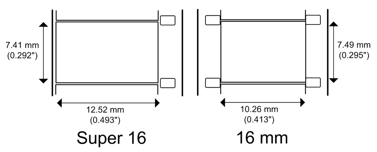
So the sound comes first, I am working in sound, audio, recordings first and want to see how different sounds form different waves. The discrete output of frames to rephotograph onto filmstrips to make reproducible sound from film projectors is a by product of this process. If you did make Sts this way you end up with frame lines which produce a horrible 24hz buzz. You could machine down the corner of the super 16mm gate to connect the frames but we are in microns here, in an awkward area. Besides, there are thousands and thousands of frames. An exposed ST done on a proper sound camera like the one at WORM is effectively ONE picture. Yes. The optical sound strip down the side of a movie is ONE picture. Its one long exposure, like a ‘Bulb’ shot.
The purpose of the breakdown is to study the graphical properties of sound within the method of variable area optical recording.
Once a thourough study has been made, the next step is to devise experimental graphical forms, where THE GRAPHIC FORM comes first, ie its unknown (to a degree) what the sound will be like.
35mm film can have two different waveforms next to each other producing stereo, then later via matrix encoding, surround sound. This hasnt been implemented in Matts code, perhaps we can set chatGPT this task. Via the matrix decoding process
you can get L, C, R and monoSurround from 2 channels. With the bass crossed-over (filltered, not out but off) at 150hz into an FX channel you get your 4:1 dolby surround, the .1 being the bass, 1/10th part of the full audio spectrum. 5:1 just adds another surround channel, effectively making it SL and SR.
Above is a frame from a variable area sound output of pink noise. Even in a long video clip of this we get a random effect, where the image never seems to be the same. We could programme Processing to generate lines with different weights, thicknesses, spacings, densities from input like atmospheric or environmental and then photograph them on the ST area to see what they sound like. I recommend reading about pink noise on wiki, cos its totally amazing, weird and mysterious. It seems that everything is pink noise, music, brains, the universe, god!
I have been thinking recently about the, perhaps deeper and more long term meaning of Nachleben, prompted by reading your new book and seeing the error in your calculation about how much time during an analogue film presentation you spend in darkness.
You say, with justified confidence (page 29 – 30) that “For a 2 hour film, you spend 1 hour in darkness“. (Suddenly Something Clicked , Faber 2025).
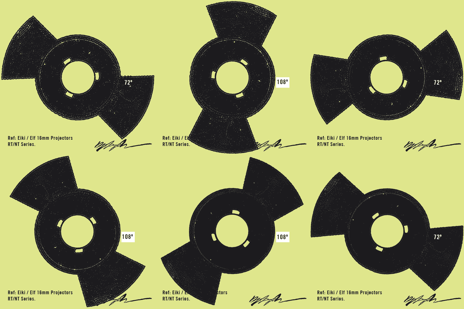
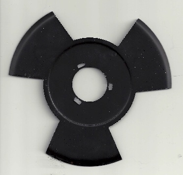
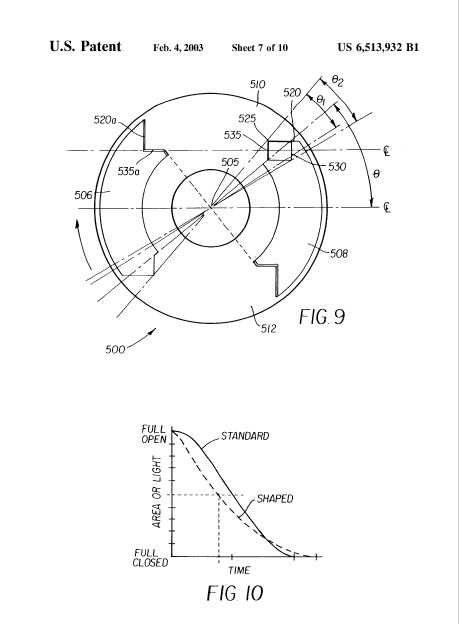
Now its easy to see the mis-calculation. You have looked at a film projector blade and seen 3 openings and closings. You then thought, well each frame is projected 3 times, so 3 x 24 = 72. This is partially right. There is a basic image frequency flicker of 72hz on a 3 bladed shutter BUT, and for me this BUT is a BIG BUT, you have made the incorrect assumption that those shutter blade sections are equal when infact they are not. They will almost certainly have a proportion in terms of light and dark of 3:2.
No I am entirely happy to be wrong. Perhaps all cinema blades are made unequal. Perhaps you could show me the projector type and make, photograph the shutter for me and we can measure it. Better still, lace up some 35mm and film the screen with a decent hi-speed video camera. Then in an edit programme, count the blacks and the images. I bet $100 the ratio will be 3:2? (BTW, have you tried this with a DCP projected, uuugggh! Its ugly, not what you think it will be).
This is a minor detail. I mean, in a 2 hour film you spend either 1 hour in darkness or 48 minutes! Who cares? In a totally honest way, it only matter to me because of one very critical issue. That is what Nachleben is, after all, an attempt at investigating, the AFTERLIFE of film and how and in what ways in SURVIVES, and in this case “what even was it in the first place?”
Its a shame because your book, if full of insightful glimpses into science and related technical fields to cinema such as the ross Cache, should be held to as high a standard of empircal accuracy than any other form of scientific research? It feels a shame you couldnt find my research as all the calculations as we read them on page 103, where the error of equal light/dark shutter openings is repeated might be wrong, or better, slightly inaccurate.
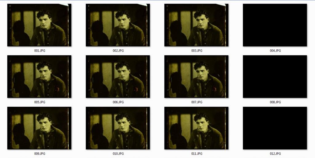
You even mention in a foot note somewhere that theres no reason why the dark phase of a cinema projector shutter couldn’t be incorporated into a digital or digitised film. Well, you might find if you tried this operation that equal light and dark openings modulating at a fixed rate like 48 or 72 hz would produce image sequences that would not match mechanical ones. This is what lead me to the realisation that the base count is 5. As you could read in other posts, this count is based on solid empirical study of cinema projector blades/shutters. There needs to be 5 frames for every 24th of a second which means the frame rate, to achive a standard 24fps needs to be 120fps!! Only recent SMPTE DCP standards do support 120fps, so maybe I should make a flickering DCP and see if anyone can screen it.
This is calculated like this. Each 24th of a second digital file needs 3 pictures and 2 blacks. The pictures are up on screen 60% of the time, the dark is up 40% of the time. The whole thing, all 5 frames needs to change 24 times a second. 24 x 5 = 120.
Cinema and ratios have a rich history. We would stand to be corrected if we said we shot a film in 1.84:1. We would be wrong is we said academy was 1.35:1. Ratios define the cinema frame, composition, historic development and technical standardisation. I’m just saying ratios define what is pleasing, what works, what provides the best light/dark balance.
My argument, that analogue cinema follows a human centric paradigm is nicely supported by a 3:2 ratio. Read this AI response for instance to the question; Cultural significance of 3:2 ratio?
The ratio 3:2, while seemingly simple, holds cultural significance in various fields, including music, visual arts, and architecture. It’s closely associated with the concept of a perfect fifth in music, as well as the Golden Ratio, which is considered to have aesthetic value in art and design. The 3:2 ratio also finds application in photography and printing, particularly in aspect ratios.
Music. Perfect Fifth: The 3:2 ratio represents the interval of a perfect fifth in music. This is a fundamental musical interval that is considered consonant and harmonious.
Hemiola: In early music theory, the perfect fifth was also known as a hemiola, indicating the relationship between the frequencies of two notes.
Just Intonation: When strings are tuned to the exact 3:2 ratio, the resulting sound is smooth and consonant.
Visual Arts and Architecture: Golden Ratio Approximation.
While the Golden Ratio (approximately 1.618) is different from 3:2, it is often seen as a harmonious proportion and is sometimes approximated by the 3:2 ratio in art and architecture.
Aesthetic Value: The Golden Ratio and its approximations have been used by artists and architects throughout history to create visually pleasing and harmonious compositions.
Classical Architecture: Examples of architecture utilizing proportions related to the Golden Ratio include the Parthenon and the Great Pyramid of Giza.
Photography and Printing: 3:2 Aspect Ratio: The 3:2 ratio is a common aspect ratio in photography, particularly for 35mm film and digital images, as well as for print sizes like 6″ x 4″. This ratio is widely used for printing photographs, ensuring a natural-looking aspect ratio.
In essence, the 3:2 ratio, while not as prominent as the Golden Ratio, still carries cultural weight in various domains, particularly in music and aesthetics. It’s a simple ratio with complex cultural implications, reflecting human understanding and appreciation of harmony and balance.
So, this ratio has been with us for a long time. Im not saying someone said lets put a 3:2 ratio of light and dark into film projection shutters because it gives film or cinema a cultural weight. Rather Im saying we arrive at these proportions when we are in tune or in balance with ourselves, with nature. Nature here being our perception, our comfort, what feels right.
And we can see, in early cinema shutters and how they developed over time, that there was destined to be a final point where the amount of light hitting the screen HAD to be tempered by A) the mechanical necessity to pull down the frame, which itself had to be masked, and B) any flickering produced by this interaction. At some point, someone, somewhere arrived at a good balance point. Around 48hz picture flicker rate, with light dark in a 3:2 ratio.
(NB, its funny you mention 3 bladed shutter as in my experince these are quite uncommon).
The digital erasure of the mechanical properties of analogue projection is what started me on the path that lead to the truth of light/dark ratios in cinema shutters. To recap, any digital moving image of born film material will erase, or write out, or ignore, or prosaically destroy, the effect that mechanical delivery will create. So, if we want digital to recreate, or preserve or conserve, or mimic this effect how many frames of black are there compared to how many frames of image?
Read all about it here, if you got any spare time. I think you might be impressed by the 1/1200ths of second fade in/out that the slicing action of the shutter produces.
“Effect of Gate and Shutter Characteristics on Screen Image Quality”, Willy Borberg, SMPTE Journal, October 1957, Volume 66, pages 623-627 (from FILM-TECH list, yet to find this online)
https://academic.oup.com/edinburgh-scholarship-online/book/22094 could be interesting but currently lingering behind academic fortress.
Commonly 35mm leaders have various frames that lend themselves for use as reference images during optical printer alignment. An example is this colour by deluxe graphic where the circle is a handy shape to see macro degree as well as left and right shift, etc.
Its worth mentioning that the pins in the camera gate can only acccomodate 35mm, but, once 1:1 macro is set up, then it doesnt matter what gates go in afterwards as it will still be 1:1.
Counters are an important control tool on an optical printer because you might want to flash a tiny spark into frame 39 or run a double exposure for frames 1138 – 2025 only. Or just keep track of how much footage you have printed.
After quite a bit of trial and error (as always) I’ve landed on a certain type of digital counter that has various features. It needs to count up and down obvs, but also needs to hold the number in memory so you always know where you are with long sections of film. With its additional relay its possible to get functions to stop at set numbers, useful perhaps for the future. One issue with these models is that the trigger control inputs are 0vdc, or ‘dry’ meaning they cant accept signal pulses form an Arduino (until I learn how to to do this). They can only accept ‘close-over’ connections that you find on micro and reed switches. The OX2 camera I’ve built uses an Arduino to control the motor so I can get around the 0vdc issue by triggering a 5vdc Relay that does the closing over.
To save me cutting a badly done slot into the lid I’ve gone for the clear lid enclosure style which I have to say I am very happy with even though it ended up being more difficult.
The switch above the counter will have a label saying FORWARDS to the right of the switch and REVERSE on the left. If I knew more about electronic systems I might not do it this way but basically the counter ‘doesn’t know’ which direction the projector or camera is running in even though there maybe somekind of circuit that does. So, you MUST tell the counter which direction you are going. This isnt a problem however because you already have at least half a dozen switches to keep track of when printing, why not add a few more.
Theres also the reset button still to do. This zeros the counter when you have laced up a reference frame. Perhaps drilling a few holes in the enclosure case is a good idea as the transformers do get a little warm.
The old CAMERA counter which works but has no memory can be used for someting else. I am going to use the clear lid style for all the counters now.
Here is some more Information for anyone who might be considering the 1 day optical printing workshops that I am running.
These day workshops are aimed at anyone who wants to have some hands on experience with an optical printer. We will be doing a variety of activities including viewing and selecting material on a manual examination table as well as 16mm and 35mm steenbecks, loading and exploring the printer and its geometry, making exposures to film, processing film and then further viewing and examination of results.
Because this machine and its processes are slow and methodical places on these sessions will be limited to about 4 people. This does depend however on what people want or expect so if there are folks with simple tasks in mind or are coming out of curiosity mixed with people with exact operations in mind then I might be able to accomodate more or less in each different mix of attendees.
This course is meant to introduce participants to the basic functions, possibilties and uses of an optical printer. The printer here is an Oxberry/Neilson-Hordell hybrid and there are 35mm, super 16 and standard 16mm gates. Because of the cost we will be printing TO 16mm b/w positive stock, either ORWO PF2 or Kodak 3303. Both of these stocks are developed in a D97 process which is easy and we will be doing these here. In future courses we could start printing to Kodak 3383 which requiress a more involved developing process ECP.
We will be printing TO 16mm and we are able to watch results on flat editing tables or projectors but the material that is being printed, or re-photographed, or duplicated can be either 16mm or 35mm. We could even re-photograph 35mm slides or b/w still negatives.
For these courses I am preparing a range of different material that participants can choose from. This is so that we can try different things and experiment and these are good ways to learn about the machine and its functions. For anyone who wants to attend I will send digital samples of the material before so you can prepare some ideas.
Of course if you already work with 16mm and have some material to use then this is also possible. Planning is a key stage in thinking through what an optical printer is used for. As they basically run 1 frame at a time they are like animation devices. My machine will run at 4 frames per second but there are reasons why I don’t like doing this. So we are not going to be producing long runnning times of film on these days. Also, as we are processing ourselves too, some dark room, hand developing skills will be required but if you are new to this then thats fine as it can be taught as well.
So, email me on lab at nachleben dot org dot uk if you are interested. If the dates of 15th Feb or 1st March are not suitable I can run these days at anytime.
7 rules:
1st Rule. The camera has a very restricted view.
2nd Rule. Everything that goes in the gate (projector gate) has already been photographed.
3rd Rule. All film stock Blackens when hit by light.
4th Rule. The printer is like an animation or stop motion camera.
5th Rule. Geometry of the picture can also be modified.
6th Rule. It’s wise to use a cribb-check list.
7th Rule. A negative/positive system must be thought about in the right way.
Some further notes or rules I have sketched out below. Please read through these as they may plant ideas and questions in your mind to explore when you come.
An optical printer is basically a type of specialised camera.
1st Rule. The camera has a very restricted view, infact a feature of its view is that it’s limited to the view of another piece of film, or an area that’s the size of another piece of film. However this can be altered by changing the lens/camera position and the lens itself and thus the field of view. My set up can cater for all kinds of lenses from
specialist copy lenses to Nikon F lenses to other types of lenses.
If a lens is of a wide enough focal length then parts of the machine become visible. And if the camera and lens are moved away from the subject enough then an area approx A5 becomes photographable.
The lens part of the camera moves seperately from the camera, usually on bellows, so essentially the system is a MACRO-PHOTOGRAPHIC set up. The projector part of the machine effectively projects the image into the gate of the camera.
When it is configured as a 1 to 1 copy, ie the height of the frame being copied is replicated in the camera, ie the subject is the SAME SIZE as the image then this 1 to 1 config is the beginning of true macrophotography. Macro photography actually make things bigger, it creates a bigger projection. In normal photography we are ALWAYS making the subject smaller, ie a person or mountain becomes the size of postage stamp.
2nd Rule. Everything that goes in the gate (projector gate) has already been photographed, or made, or processed or all 3. So thinking through what you are preparing or pre making is key in planning what you print. Elements in the gate can be changed but then print to the same continuous piece of film in the camera, a kind of crude editing but they can also be exposed over the same piece of film by rewinding the camera stock to an exact position, changing the target film and re exposing. This starts to resemble the compositing process and we will be looking at this in future advanced courses.
Its important to remember that the printer can make negatives or positives. It all depends on your overall workflow. It could just make a positive from a cut or series of negatives. It could make an internegative from a cut or series of negatives (this stock is only available on 35mm however, Kodak 2234). It could produce ‘elements’ like mattes by copying neg mattes to make their opposite. etc, etc.
3rd Rule. All film stock Blackens when hit by light. So following this rule when we RE-film a negative we will get a positive NO MATTER what kind of stock is our raw stock. But there are differences between negative stock and positive stock. One obvious difference is that negative stock by way of its use in a shooting camera has an exact ISO value. Positive stock however has no real published ISO value, if it did it would be very low, something like 4 or 5 ISO.
This is because the printer has a light built in that is bright. Infact it is usually too bright
and we use ND filters to bring it into exposure correction range. So when printing to positive
stock 2 things are important. 1 a wedge test on target photographed material , 2 ref to the
process times as a longer dev results in steeper gamma curves, ie more or less contrast (CI
contrast index) which might be factors in the look we are striving to achieve.
Coming back to printing negative material onto negative film. Kodak 7222 for example has an ISO value of 200T, so to get a correct exposure we will need a lot of high value ND filters. Now
negative film is also slightly more fragile and scratch sensitive whereas positive stock is
meant to run through a projector so naturally if we want a legible b/w positive made from negatives that we have shot then we print to a positive stock like PF2 or 3303. The lamp is typically run at 90 on the dial. As its a tungsten lamp, it’s optimal , white light output is achieved at this setting. If the lamp is turned down (for eg instead of using ND filters) the colour spectrum changes significantly which becomes a problem for colour film especially.
Well, I say ‘problem’ but Artists use materials and tools at their disposal differently from the idea of ‘Normal’ or ‘Correct’. So you could exploit this colour spectrum change in creative ways.
4th Rule. The printer is like an animation or stop motion camera. It only takes 1 frame of film at a time. It cannot run at sound or silent live action speeds like 24, 18 or 12 fps. It can
take a picture manually when you hit a button OR it can automatically take pictures in sync mode when a specific switch is thrown. In this mode (on my machine currently) each frame in the gate will get photographed once by the camera continuously.
1 to 1 shooting will result in a basic copy of the original albeit in a different, ie positive
format (if we have loaded positive film stock) and if the geometry is set up a certain way.
5th Rule. Geometry of the picture can also be modified by virtue of the fact that the lens is movable. It can move fwd/bkd which will effect focus. It can also shift up and down and side to side. These lateral movements have the effect of shifting the image, like
shifting the subject, whilst the camera remains fixed. These movements can be employed when doing something like composting smaller images within the frame, ie a twin screen 16mm, side by side composite which is a format often employed by the avant garde.
6th Rule. It’s wise to use a cribb-check list so multiple things can be set right before
shooting. It’s also a good idea to make an exact plan on what you are doing, including detailed
outlines of settings and sequences. This is because when the film is exposed and you are looking at it on a steenbeck you need to know exactly what the settings were on any part of the film. This is especially crucial for early wedge and ramp tests where the point of the test is to zone in on the look or image aesthetic that you want. Once you have ascertained the settings you can run a longer sequence.
For example heres the check list I use.
PRINTING CHECK LIST
A. Raw stock, laced, checked. 90 frames clear. ZERO on counter
B. Target film laced, perforation/splice damage check. ZERO on counter
C. Further Target material prepared….
1. Focussed / Aligned / Framed
2. Rack over
3. Take Ups check
4. Lens F stop
5. ND check / plan
6. Lamp at 90 / room light check
7. Camera speed / direction check
8. Camera shutter check
9. Counters set (note camera frame value)
10. Projector direction / speed / mode
11. Sequence plan
during shooting
12. Camera take up correct
13. Camera digital / mechanical counter match
14. Projector digital / mechanical counter match
15. Is the kettle on for tea, etc
7th Rule. A negative/positive system must be thought about in the right way.
A negative, whether its from the camera (OCN), or an internegative (IN, duplicate of an IP) transforms into a positive, legible, readable image when it is either contact or optically printed.
Making ‘prints’ from negatives is a ‘PHOTOGRAPHIC EVENT’ in its own right, the completion of the abstract phase of making photographic negatives. I argue for the conservation of this event as central to the survival of film arts. Scanning a negative and mathematically inverting it is not equivalent in any way to the photochemical event of printing. I can think of a few feature films released in cinemas that were shot on 16mm and scanned to a high resolution, digitally inverted, graded, etc. To me, they look extremely flat, planar, like something with infinite shallowness, ie no depth or physical properties, the residue of these forms like water marks, scratches, surface artifacts are all over-amplified by the digital sensor and thus rendered incompatible with the promises set out in the first place by analogue. If its a DCP, then its even worse as there is no flicker.
Think of it as rendering. If you cut up a load of OCN into a sequence you like, you can make positive prints from this edit. If you make an in-camera 100ft film on negative on a bolex with no splices you can either print this film to make a projection copy positive or if you foresee the need for many prints, you can make IP/IN copies so that the OCN material is kept in good condition as running negatives through a printer, or any machine will produce wear and tear.
The neg/pos system is being employed again here. The Orig’ OCN is being copied to an IP. An interpositive, a positive image on a negative (orange hue) film stock base. Then if this is printed again, it will be an internegative. We are always going from neg to pos, pos to neg like making molds and then casting a new form.
So the neg/pos system are two sides of a single coin. One is not complete without the other. Forget ‘reversal’ film for now. Reversal film is just a way to get a positive image as quickly as possible from the camera film which is infact what it is. It was developed for amateurs and the home movie market because home movie makers didn’t or couldn’t use a neg/pos system and it was thought that home movie makers would not need dozens or even hundreds of copies of their films which was right, they didnt!!
There are some exceptional Artists who work with and use Reversal film in a process that involves printing or copying (Gaëlle Rouard comes to mind) but the unique artifactual value of the finished film just goes up and up the more this process is followed, and final films are projected adding to the deterioation. Perhaps life is too short to worry?
If you want to mount your camera on a tripod or other device and you want it to pan around the optical axis you will find that the mounting holes on the flat base are NOT on this axis.
This may not be anykind of issue for people but for me its a disaster. So what is the measurement from the ‘line’ that the 3/8 and 1/4 holes makes (RED LINE) to the optical axis (GREEN LINE)? Does anyone know? Yes, just measure it you say. Well, where are you measuring to, by sight, to the middle of a marked safety cap maybe, to the centre of a marked safety filter maybe, etc. Surely this information is known by Bolex?
Anyway, I’ll measure it for myself and publish it here…. 17.7mm.
107mm, height of Op’ axis above flat base
Last thing to fix before getting on and shooting tests is the take up power suplies for the 120V/AC motors. Budget restraint means I’m using cheap electronic transformer/variac but it seems to work. Ideally I’d like to design somekind of clockwork mech for the mag film tensions because its hard to make this camera portable with a 120 volt supply. The camera motor and PSU can run of 36v and I’ve built a PSU that uses 2 x Makita lion batteries. Seems crazy to need 120v just to keep film on t-cores so clockwork is the answer.
(NB) Alright its not the final thing. Im actually just designing a viewfinder that uses the boresight access hole on the optical axis of this camera. This camera is a NON-reflex type, its also not even a rack-over type. Once you compose, you need to fit the sprockets, load the film and work blind!
Finally fitted this nice perspex door for the projector head on the printer. Will keep things nice and clean and protected over the coming busy months.
Platter cinema system tables are big pieces of aluminium with curved sides mounted on rigid spokes and a decent bearing. I’ve had them kicking around for years and they started forming ideas when I was thinking about how to employ them creatively. So I’ve got around to mouting a vertical one against black. Next will be some maths and geometry and figuring out dimensions and works. Ive got one I painted black as well. I will also be making a horizontal mount for other ideas.
An oxberry optical printer and rostrum stand often use very similar cameras infact there is very little difference between them.
An optical printer images the target upside down in the gate so you thread it in the projector the right way up. This helps you see what you are shooting. Its printed in the gate as if it were being projected so if you print to POSITIVE stock its ready for projection once it is processed.
However on a rostrum camera the artwork or the flat pegbar area infront of the operator is correct for your position but infact as a target its upside down if follow the system above for an optical printer. This means it gets imaged in the camera the right way up which will cause problems. Now, if you reverse the teeth (this is all for 16mm btw) on the camera sprocket and load the raw film in the normal take up magazine and run the camera backwards it will orientate the image onto the emulsion side at head of the film so the film can then be printed as above.
This can be seen in the crude image below where the little stick man on the bottom left is a person working at the peg bar artwork table.
Then, as in this video below, we load film from take up mag, reversed by sprockets and run in reverse (it runs forwards here just to load ref mark into place) we get an image orientated as it would be in a normal camera loading ready to be printed.
This is hopefully the last time I post anything specifically about these motors and their applications. I thought, seeing as all the main functions are working that I’d draw up a plan for the whole system so that anyone can use it for themselves.
My application is simple. I want to drive ths camera with a motor that lets me control speed of rotation. 360 degree = 1 frame of film exposed. This frame is fired by a button like a shutter release.
Heres the camera with a rival motor system, an old Oxberry printer drive. It actually hooks up and works. It runs of 120v and has 2 speeds. The solenoid fires at 35v odd and slips a clutch which then engages the camera shaft and fires off a frame of film. However on the negative side, the motor is noisy and has a loose bearing so it could produce quite a lot of vibration which is undesirable in animation. It is bomb proof but I am super curious about closed loop stepper motors and what they can do.
Heres the stepper motor. I wanted something beefy that had enough heft to drive the camera and not ever struggle. Technically if you match the Nm torque needed to to turn the camera over with matched stepper motor you end up with a small motor. I dont trust that such a small motor can do the job. This motor’s holding torque and other specs are plenty for this job. Closed Loop motors have an inbuilt encoder with connections that are made to the driver. This means that when powered and when it is resting at a signal pulse position it will not deviate from this position and if you try and turn it away, which takes some force, it will spring back to where it should be. If you disconnect the power you can freely rotate the motor which will be required when threading or lacing the camera. BUT, once you have done this, you need to position it back in a ‘true’ position or else when powered up again it will make a tiny snap to the nearest resting place. This is tweaked by programming the arduino which we will see later on, but basically you can make it step tiny amounts 1 at a time and thus you can align it this way.
Heres the Arduino UNO sitting on the driver which is a CL57T by stepperonline. On the right are control signal wires from the UNO. Multi coloured encoder wires from the motor and the brwn/blue 36VDC from the PSU.
Heres the motor in a vice to test and then the motor offered up to the camera with temporary mechnical coupling. Below is the PSU.
Below is the button unit I bought that has a few options that I can exploit. The red STOP button will interupt the 36VDC so that I can turn or thread the camera manually which is required for oxberry gates. The white button currently fires a frame. The black button, well, what could the black button do? On the UNO board (I will post a proper schematic soon as) there is a green LED, a red LED and a pot. The pot controls the speed of rotation. The greed LED lights when the camera has stopped. The red lights when the exposure is happening. The button wires also come into the board. The whole circuit is EXTREMLEY simple. Below is a video of the button firing a frame
For the observant amongst you, you’ll notice that the button is pressed twice! This is me trying to programme a BULB setting by putting only 50% or half of the correct turns into the Arduino sketch to get a full rotation. This motor has 200 steps per revolution set to 8 microsteps which means that 1600 steps = 360 degree = 1 frame. However if you type in 800 then the motor only turns half a rotation meaning the shutter is OPEN. Then when you press the button again it turns half again thus completing a full turn. On Oxberry movements careful attention must be paid to the pin registration phase of the cycle so that the film is being held correctly. The great thing about Arduino is you can make these changes, upload and have different functions in literally seconds. There is no need to design and plan and write some great big application that does all the things you think you will need. Below is a video showing the motor coupled and me making a speed change whilst listening to the Titanic series of podcasts by the Rest Is History blokes. What Im telling myself here is that Ive turned the pot down. When the pot is turned down the values it feeds the Arduino effect the way the motor is driven. I’ll post the code below in full but basically the pot gives a range which is usable from slowish to fastish. We dont need to be dealing with exact shutter speeds yet but we will come to that at some point. Faster speeds are unwise to test with the temporary coupling because the motor will easily slip out.
The motor is driven by using micro-second delays between pulses of 5v effectively to the driver. So you can very accurately make timed rotations in milliseconds. But, the shutter is not just an open disc. It itself can be adjusted and its OPEN angle is 170 degrees. So for a rotation of any given value in time, only some of this will be an exposure. Ive been simply using high speed video footage to measure the shutter speeds on the other Oxberry. But as that is usually used for printing its not critical. This unit I plan to use as a camera so will need to dive into absolute shutter speed vlaues at some point.
Heres the completed camera. A word on shutter speeds.
We can ascertain from the arduino programming how long a 360 rotation is.
We then divide this number by 360 to get time per degree. Then multiply by 170 (or another shutter angle) to get the exposure speed.
I will also do some hi-speed video as this gives an absolute visual record of shutter speeds.
For all use fomr here on, it might be useful to do the maths to create common sutter speed fraction values, 1/2, 1/4, 1/8 as well as 15th, 30th, 60th, etc.
Heres the electronics. Theres tons that can be added like speed selector buttons, second switches for DIR, etc. But for now I like the fact the function is baked into the
Most of the cameras I use (and projectors for that matter) are driven by a motor where one full turn, or 360 degrees equals one frame of film (they are all optical printer or animation cameras).
There obviously needs to be position accuracy because the camera needs to be closed when the motor has spun 360 degrees, made its exposure and comes to rest, ready for next frame.
The way this is achieved varies from camera to camera. On the Oxberry, the motor is an expensive ‘pancake’ style printed armature motor. Its spins very smoothly, has zero ‘cogging’ and other features. Its position is known to itself because of an optical disc that stops after each rotation. This is handy BUT what if I want super long exposures. And, to replace this motor is cost prohibitive.
Enter Closed Loop stepper motors.
These systems have really improved in recent years so now for less than £100 you can get the motor, the driver and the PSU. To operate the motor, ie to make it spin, a microcontroller is used such as Arduino or Raspberry PI. I am using an Arduino.
The functions which the motor will be programmed to perform can go way beyond that possible with the motor system on the optical printer. However, the printer can extend its functions by also being controlled by an Arduino and I am working on this aswell.
For this experimental animation / plate / studio camera I need a way to control exposures and position as well as other possible inputs like the postion of objects being filmed.
I’ve dug out the beast and next need to design mounts that place the camera at the nodal points. These heavy geared heads were really useful in the old days when your cameras was also heavy. To machine something like this now is cost prohibitive but thanks to digital ‘progress’, you can buy them if you are lucky enough to see one for sale. I dont like the design of the top angle plate, held only by bolt tension. Decent heads have a pivoting shoe design that has mechanical rigidity. If a heavy camera slips on these tensions it could crush your hand or a finger.
Back to the Arduino programming. It’s hard. Thats because I’m not a programmer or coder and so I have had to start at the beginning with getting an LED to blink. Some deme code to make the motor run has kept me busy as you can see below.
Quick wish list function table……………..
MODE
FUNCTIONS
SUB menu
Inching
manual turning to thread/unthread film
motor psu-
Zeroing
Bring shutter into correct position
count?
Single Frame
Push button single frame / manual / speed options
(speeds)
‘B’
Push button shutter open/close / manual
‘B timer’
Push button shutter open/close / programmed time
(Time)
Reverse
Prepare for reverse / shooting / frame find
(speeds)
Rewind
Rewind to set frame
Frame #
Single Frame / SP
Single frame exposure on special event / input
(speeds)
TimeLap
Programmed single frames and intervals
(Speed & Time)
Cont’ Run
Set frames, speed, running 12fps MAX (???)
Then, after NIkon F mount plate is done we can start Rotoscoping to our hearts content.
To get this camera working I’ve managed to hook up another Oxberry part, actually a 2 speed projector drive, seen below.
The motor runs on 115v ac and the solenoid fires at around 36vdc. When the solenoid fires it allows a clutch plate to slip thus engaging with the driven gear shaft and momentarily (ie 1 frame) turning the camera drive shaft which equals 360 degrees and thus 1 frame of film.
Although this will ‘work’ and allow exposures to be made it has limitations that that conflict with sonme of my planned uses, specifically long exposures of several seconds and sometime minutes. To afford these functions I have invested in a closed loop stepper motor.
After all this the last thing will be to get the Nikon F mount at the correct distance from the film plane.
I have already tested this distance to check lens function by rotoscoping and all is well. This camera body has a boresight opening which may allow some kind of framing as long as the sprocket drive is removed.
However, Im not so obsessed with this function as I Like the idea of framing by projecting a small piece of clear film and seeing whats in the frame and where it is. It will be a heavy thing when finished hence the geared head I bought a while back. My planned uses Im gonna keep under wraps for now but just to say it will be a kind of studio / plate / process / animation camera for both 16mm and 35mm. Interestingly the camera body has an 8 perf opening by the gate so, using a vistavision shuttle one could expose portrait format 8 perf film!
Table for ND filter set. Made up from only 3 gels. Half stop gels are sold by LEE. Can do 21 stop wedge strips then.
filter #
stop
# gels in frame
# gels in frame
# gels in frame
Optical Density
% Trans’
ND0.3
ND0.6
ND0.9
1
1
1
0.3
50
2
2
1
0.6
20
3
3
1
0.9
12.5
4
4
1
1
1.2
6.25
5
5
1
1
1.5
3.12
6
6
1
1
1
1.8
1.56
7
7
2
1
2.1
0.78
8
8
1
2
2.4
0.39
9
9
3
2.7
0.19
10
10
1
3
3.0
0.09
11
11
1
3
3.3
0.04
12
12
4
3.6
13
13
1
4
3.9
14
14
1
4
4.2
15
15
1
1
4
4.5
16
16
2
4
4.8
# gels in frame
# gels in frame
# gels in frame
Shutter speeds /deimos control. Need to double check by shooting some hi-speed video on phone.
shutter angle
Deimos setting 1
Deimos setting 2
Deimos setting 3
millisecs
640
340
250
fraction (using above)
16/25
17/50
6/25
170º
1/2+ of a sec
1/4+ of a sec
1/5th of a sec
85º
42.5º
21.25º
frames open/HS 240fps
140 frames (7/12ths. 1/2+ /sec)
66 frames (1/4+ /sec)
48 frames (1/5th /sec)
Owing to the hybrid and vernancular nature of my printer, the camera speeds are not set the same as on a proper Oxberry. The Oxberry printer head has 4 speeds set by a gearbox effectively. However, the faster speeds, say 4/second will cause problems when used with Deimos speed 1. Thats because that camera speed is only 1/2 a second so isnt fast enough to keep up!! Even though much ‘faster’ shutter speeds are possible on the camera by using the adjustable angle, the FPS speed is independent of this.
There might be a case to rethink the master-slave direction in my system. Currently the projector is the master. It triggers the camera. It dictates the sequence. Is it possible to reverse this? Could the camera dictate? Then, if fast projector speeds are set, all it does is load a new frame quickly, but camera is always prioritised? Its interesting that it works either way. So its like two different modes.
LUX IN GATE READINGS (only made 7 filters……..)
(NB Because its not a probe meter, readings for lamp vary considerably. Need to devise registration method)
Filter
T 2.5
V 90
Con’ Light LED/ 1M – LUX
Printer – LUX
FF
OD
No filter
900
19000
#1
370
8000
2
0.3
#2
210
4200
4
0.6
#3
140
2700
8
0.9
#4
80
1600
16
1.2
#5
37
740
32
1.5
#6
21
420
64
1.8
#7
11
230
128
2.1
#8
#9
#10
#11
Speeds expressed as % of full shutter. Open RED, closed Green. Speeds 1, 2 and 3.
So after finally setting the lens stage and getting the camera drive working I’ve been conducting tons of tests to ascertain exposure settings for different stocks, processes and target outcomes. The first is really to get a good method established for printing negatives to PF2 and 3302 using accurate & repeatable D97 processing.
As the original materials I have to use are themselves also varied interms of calibrated or reference its a matter of getting a quick ‘acceptable’ result, taking into consideration the nature of the original, and aiming at shooting at T5.6 or T8 and then taking a lux measurement in the gate, with transmission through the target, to enable setting up a quick wedge test for any material going to the stocks mentioned above.
Once I have a good density positive at the lens mid point, further tests can be done with shutter angle and ND filters to tweeak the results plus of course processing factors such as dev time and contrast etc.
Its amazing how much light you have to stop down to get results in range. I am lacking a decent set of ND filters so am busy making these from glass squares. (lighting gel is fine, dont need expensive camera filters).
I’ve loaded the camera with 400ft and just snip after the sprockets after each test. That way I can respool, move fogged frames out of the camera and be ready for another test very quickly.
It’s crucial to process D97 accurately and repeatable for tests. Tweaking this stage comes later when chasing specific effects.
Also its super important to log and document each test, what each tests carries out as this info is needed after to determine which factors are responsible for which samples. For instance in one test there was a few flash frames where the image looked good, better even then the tests, but it was somekind of accident as it didn’t follow my test sequence. I dont know what happened so cant repeat it.
Im shooting a single frame Ive chosen for a few reasons. Its not helpful that I am copying a neg that is itself actually on Agfa ST8D, a hi-con sound track stock. The image is sharp, but will not produce a full range of greys. However, Im after a subjectively good looking result so it doesnt matter. Other tests can be done shooting negatives in controlled conditions to generate reference material.
I have of course unconvered some new annoying issues such as the fact that the viewfinder glass does not seem to correspond to the camera gate, which if true is disastous and may need lengthy rectification. On the whole though the whole system is coming on well and for once Im too busy to get around to uploading this blog.
Well, cabin in the corner of the garden anyway. Trying to crack on with this so that anyone who wants to come and work at Asylum or my studio can stay here. Anyone who doesn’t want to work here can stay as well because that is what friends are for. It will have double bed, woodstove, a fax line, morse code terminal and electrification. Guests can use the house WC and the plan is to build an outside kitchen and traditional Cob oven. Im naming it ‘The Library’ because I’m ging to fill it with books, 95% of which are about cinema apparatus, film theory, experimental film and the other 5% is about Toads.
To see if the sync 16mm system worked I made up two identical loops with the exact same frame marked. Amazing when it worked but slightly dissappointing when it didn’t.
The whole of the workshop/studio has been planned around an central, empty space and a free wall. Everything like filing cabinets, sets of drawers, storage has been bult on wheels so can move out into the corridoor for more room. I finished the overhead scaff riggin the other week for lights and flags. Few more tasks on some machines then I can start making things.
I made use of the Mag follower by using its 19″ racking for the amps and Eqs, for the sound from both the steenbecks. Keeping this area tidy and free of cllutter is crucial when editing material gets hectic.
Its official. I hate this thing. Its SOOO unreliable. This time however it might have got damaged when some drilling took place on the frame of the printer. Looks like the bridge rectifier has blown! It can be fixed (my electrical friend tells me) but I hate this box anyway. Ok, it does an important job. It controls the motor which drives the camera on the Oxberry. This requires a stable 18volt DC supply for a duration controlled by the motor feedback. The motor is hugely expensive to replace but modern drivers do exist but they are very complicated to set up. Lots of people just run these machines with modern stepper motors. Also, when I was testing the motor to locate the fault I managed to fry the logic chip on the motor feedback board. Great! So currently no camera!!
I came into work one day and the fairies had been busy. Because there on the lens platform was a new lens x and y stage drive rig. Also it had a T-bar plate so I could mount lots of different lens plate holders.
I immediately marked off all the basic optical processes ie 16(35 to 16(35) which uses same setting. 16 to 35 and 35 to 16. This took most of the day but now its all marked it will be quick to find the settings again.
Ok, its only been about 10 years since I made these negs and never got round to printing. Who cares, I’m in no hurry. Sometimes ideas take a long time to develop as well. The idea here though was quite simple. To make sound recordings on the Eurocord-Klangfilm, then document the machine itself.
The manual table is really the best and most satisfying method of going through films to catalogue, inspect, repair, select, prepare for viewing or copying or projecting. Its film nearly at its most peaceful.
Ive got loops and stuff but my lens of choice to view strips of film are Bell&Howell 60mm lenses that you find on the 16mm projectors. The table area is a bit cluttered so I am going to make a shelf on the wall for reels, splicers, tape, etc.
My 16mm print of ‘Dream of Wild Horses’ by Denys Colomb de Daunant looks pretty faded. But maybe it wasn’t in full colour originally anyway. So can it be restored photochemically? We will see.
Added the sound head block to the Matipo to check fixings. Slight deviation from the neat film only path but should work once I work out the voltage to the light.
My studio practice, when I get there is going to involve smallish table top stop motion animation, diaramas, mattes, experimental set-ups and lots of rotoscoping. For all this you need lights. Good old BB-list delivered these nice 1k fresnels in the end. Ive got some old Mole-Richardson 2k fresnels on stands, lots of overhead lights like Minim F’s and Preludes, redheads and PAR36’s. All tungsten.
It is well known that flat table editing machines can be modified into contact printers. All that needs to be done is to black out the screen and any light leaks from the cabinet. Make somekind of slit that covers the prism and mask off any light straying out from the prism block. You then load your neg on the mag-stock platters and through the image gate and your raw stock following the usual film path. Emulsion to emulsion. The light passes up through the prism, through the slit, through the neg, through the raw film.
The two sprocket drives need to be engaged so the films run together. Ill document the gate assembly here as it will involve some engineering and adjustable slits. Just changed the fan in this machine. All I need to make it FWO is a new optical sound head. Lew!!!!
Just been servicing some of my own Eikis for the Bristol 16mm stuff in a few weeks. Two of them fit in the flight case that the geared head came packed in, just without lids. The RT one has been playing up for ages with a problem with power to the exciter lamp. I’ve got a few of these projectors and have started a spreadsheet detailing serial numbers, condition, works, etc.
My film, ‘Me at the Zoo Too’ is an attempt at thinking as the medium of film.
It depicts, or rather interprets, or rather ‘thinks about’ the first ever youtube clip to be uploaded, the celebrated and widely written about ‘Me at the Zoo’ by Jawed Karim which has currently had 270 million views and counting. It was uploaded on 23rd April 2005.
My concept involved transfering this clip to 35mm motion picture stock as a way for the analogue photochemical film material to ‘quote’ or comment on not just the clip itself and its place in history but also the whole system of online video and user defined video.
Simplistically seeing it as a moment in the history of moving images therefore necessitated its archiving and preservation for the future and the best technique for this is motion picture film.
The clip is very short, 19 seconds. In my film it appears twice.
In the frst clip it appears as a very small, stamp like image in the middle of the frame.
The size is not arbitrary. In actual fact, its the relative size in pixels of that first clip (320×240) within a full frame 35mm image. To be projected properly it requires a cinemascope gate or aperture plate and the correct lens for scope BUT MINUS the animorphic adapter. In effect it is the same as for a fox movietone 1.19:1 film, a film with full frame and optical soundtrack.
There is then an interlude to change lens and gate.
The second clip is sized according to a DVD video image (720×576) within a widescreen (1.85:1) frame, hence the cropping. On the screen the grey coloured area is masked out by the aperture plate so there is an argument to keep it black. But, film is not ONLY projected, so I wanted something to indicate all the factors at play. The sound is mono, printed as a cyan VA optical soundtrack.
These different factors are variables afforded to or intrinsic to the film medium. Therefore they act as parameters that add some level of interaction with the clip that is forever recorded into the piece of work.
The QR code at the start is a link to this website. It only occurs for 1 frame though so references the manual viewability of film, ie a when a person handles the film to rewind, examine, etc.
An error occured during the digitisation of the clip (wrong colour space defined) which has resulted in a weird colouration. It looks more grey than it should and there is no blue. I quite like this though because the presence of Elephants is an important conceptual one.
Another idea for how this work engages with the notion of the internet is what happens when it is viewed in cinema spaces.
The online original has every viewing counted and logged. As an artifact, outside of that system, individual viewings can not be easily counted (ie a print projected infront of an audience) and so the qualifying value must reside in some other (than metrics) dimension and I would argue this is the social basis of cinema.
So screenings of this film in cinemas or galleries to a congregated public, are diametrically opposite online viewings.
Another aspect of this idea is that it could be exhibited as an object. That is in a vitrine or diplay case with notes etc.
This is another dimension afforded to analogue mediums like film. They are objects and artifacts that can embody an idea or concept in multiple dimensions of time and space.
It comes with projection instructions if anyone wants to screen it. Two copies have been made. I am considering getting more made using the correct colour space.
I am working on other films and Art works that use similar concepts.
Me athe Zoo Too formed the ‘practice’ component of a MRES (master of research) that I did at UWE which had as one of is aims to explore how a film archive / lab can act as an experimental production mode.
Like anything in an interconnected world I start to prepare and finally paint the floor and get disracted by old electronics. This is the way.
I blew a part on my sound follower a few years ago. I had turned it on to check functions and work out how it worked and then a little pop happened and a puff of perfect white smoke rose up from within the PSU block somewhere inside the machine. My thoughts then, after looking closer at the board concerned was ‘what chance is there of fixing this?’.
Well, several years later, I’m clearing the workshop to paint the floor and the sound follower is stood there on its own. I think, fuck it, lets have a look at this thing, partially spurred on by the success with the Kinoton spark circuit. After removing the PSU block and taking a closer look at the blown part I can see that its easier to get to and remove than I first thought.
Anyone had much experience searching for old manuals online? Well, you get these companies that bought up loads of service manuals and now sell them off for what feels like silly money. I found a complete manual including schematics for a similar-ish model to mine and thought it would be worth the risk of getting it.
I was very happy when it came because it had everything I needed plus more because it was also an opearation manual. I challenged myself to find the correct schematic and part ‘before’ I consulted my electronics friend.
What we are looking at here (took me a few days to decipher the manual and its detailed outline and indexing system) is a part of the PSU circuit where there are 3 relays. rel.1, rel.2 and rel.3. I knew that the blown part, after extracting it, sat between two relays, most probably 2 and 3. I also know, or had learnt from my friend that the part was a RIFA which were known to blow because they allow mositure in. You can find umpteen stories on the internet with radio engineers and electronics folks waxing lyrical about when it happens to them. They act as noise suppressors across mains lines in audio equipment. Easily replaced by modern ceramic caps.
The manual also shows some additional parts (which I dont have) that I guess I’ll be chasing for the next twenty years like this optical sound reader.
You may well ask what is the point of this machine? Dont! Don’t, you understand! Don’t ask this question, never ask this dumb question. Its a machine and it needs our love and attention. It did a job, a good job back in the day and theres absolutely no reason for it to retire from this job. It was built by human hands, designed by human minds, run by human skills and enjoyed on the cinema screen by humans!! What more fucking reason do you need.
So after some successful use, the right hand side projector xenon lamp has started to refuse to strike. Each time it is struck it blows the 6amp fuse on the lamp house. Having experience with igniter units, tesla coils and the scary electrics involved I was fairly pessimistic about being able to fix this. Everything inside the lamphouse looked in good condition.
At first we thought the spark gap had popped because the right side machines’s clear chamber had frosted. However we learnt that this is normal.
But then a good friend of the Cube turned up and looked throught the circuit schematics. He ascertained that the assembly responsible for handling the mains to DC handover and the initial spark might be the culprit and offered to remove it for a closer look. Underneath was some carbonising which would exlain the failure to work. He took it away and cleaned it, repaired (already badly undertaken repairs) and resoldered. After we’d put it back in it fired up and all is good now!!!
Before.
After.
Heres the newly soldered component set and the two lamphouses undergoing checks and comparisons.
Really getting fired up and excited going through loads of resources at film labs website.
I havent looked at their website for a while so am blown away by all the work thats gone into this. Theres literally everything there you need to shoot, develop, project, etc motion picture film. Amazing, great work guys, keep it up!!!
Im giving a talk at this festival. see below. I’m revisiting some of my research that came out of the work I did on digitising the Curzon Cinemas nitrate clips. This involved looking closely at the mechanical operation of flicker as it occurs in reality in a projector in a bid to resist the erasure of a film projectors presence in digital file versions of film born material.
This is my chance to do a proper job aligning, leveling and improving this machine. From previous set-ups I’ve learnt a lot about what is wrong with the design. Heres a load of snaps showing the awkward assembly of the projector on two steel rails that just bolt to the top of the main frame. This part of the machine has to be assembled section by section as the machine screw location tolerances are high so its impossible to bolt together if you are also lifting/wriggling it around.
This could be improved by a new frame that spreads out more and includes screw-jacks to dampen/support the circular rails that the lens and camera move on, which wobbles like fuck, even when all locked off.
Heres is an older oxberry camera block than the one mounted on my frankenstein optical printer.
This camera has no rack over viewfinder. It has a voltage controlled movement and adjustable shutter angle. No viewfinder seems like a problem for a camera. How on earth can you compose, focus, even see what you are shooting? This camera will be used as a camera for matte work where other plates (film elements) have been shot elsewhere by another camera. These plates are laced into this camera as if it were a projector. When the image is projected it will allow an image to be framed, traced, focussed. Once this is all done, raw film can be swapped in and composites shots can be exposed.
It has a 35mm gate and sprocket movement. It also has a standard 16mm, 2 pin gate! Finally!!! All in all its in very fine condition. Some work will need to be done to get the electronic controls working. Heres a bit of double pef film in the gate. Of course, if I wish to shoot onto single perf stock I will need to remove one set of pins. But this gate would be better suited to copying, or duping by holding material on double perf film
Heres some pictures of the prep for getting a lens onto the camera.
The Nikon F plate held infront to check focal range.With a light source inside the camera (rotoscope mode) and a gate wth piece of film in we can project an image. Also check the Nikon F focal flange distance = 46.5mm The image is correct of course because we photograph work to conform to projection
All that is needed is to machine a block of alloy/ali to fit the front machine bolt locations, put in a Nikon F bayonet mount, space and align the plate correctly and paint the inside black.
OK. So I am very happy with a new pair of 1000ft mitchell film magazines and here is one sitting on top of the animation camera. However, these mags have a wider base fitting known as NC (newsreel camera) and the camera uses one called GC which is smaller. Just waiting to hear from someone in LA who has an adapter. Hopefully not to expensive.
These mags are for the eventuality when large runs of film need to be exposed, possibly towards final prints for exhibition. Magazines can also house exposed film for certain operations such as long runs of rotoscope material, or at least longer runs than what 400ft reels can afford.
1 : the remains of something broken down or destroyed digging through the storm’s debris in search of survivors sifted through the debris of his flooded house. 2 geology : an accumulation of fragments of rock. 3 : something discarded : rubbish picking up debris after the parade.
I am hoping to hold an exhibition at my studios next year. It will be a mixture of sculpture, video and installation and will reflect on decades of collecting machinery associated with Cinema.
In marked contrast to Expanded Cinema which largely aims to enlargen conventional applications of projection technologies (albeit in inventive, experimental and innovative ways) my aim is to celebrate the metallic presence of film machines as artifacts, sculptures, bodies.
Through simple and crude reinterpretations and reimaginings of their design, aesthetic, function and mechanical operation, objects will explore the inner space of their own legacy of purpose.
Alongside these sculptural works will be several moving image works including one made using a 3 colour b/w seperation film preservation technique.
It struck me recently, when unloading a final lorry load of gear that all these strange objects and parts all have their own sculptural presence. And when some are combined they take on new forms that contribute to an extension, an expansion of their lifes, or afterlifes. That is they keep giving, even in advanced redundancy and obsolescence they provide ideas, materials, toolsets, techniques, functions and value, that are far from exhaustion.
An old carbon arc mirror for instance, used in pre-XENON eera lamp houses finds a calm place when combined with the crudest light source, a candle.
Or here, where a cinema platter table, used to manage 35mm prints in cine-multiplexes combines with a completley stripped down steenbeck frame. Any use value or functional purpose this editing table had in a previous life is now dismantled to reflects it core being, a big metal welded frame that can act as a base for all kinds of projects.
I will construct a new version of this arrangement where a large horn speaker, used as the centre speaker for over 10 years in an old cinema in Bristol is combined with some heavy studio ‘legs’ or tripod which I was gifted by the late Dave Borthwick from Bolex Brothers animation studio.
My old friend, the Kalee 21 (above) that we ran at the Cube Cinema from 1998 to around 31st January 2016 will be placed, like a bust, on a plinth inside which I might try and build a loop holder (like a Kinetoscope). It will sit on some scales as if to weigh its soul.
None of these objects is in fact ‘junk’ in any way. Their reorientation as objects in a gallery show is booked into their diaries. The rest of the time they are all employed in other ways, some reflecting their designed use and sometimes revealing re-purposings.
I have in mind about 10 pieces and am working from now until next year with the exhibition planned for March possibly.
I will use this blog as a diary/note book/sketch book/scrap book as I go along to document the whole process.
Down by the river Dart last week looking and listening to the Bats I took some photos using an LED torch and my phone.
The results are ok, but when you look closely they are really blurry, stroby and uneven. This process of looking at night time really appeals to me and I will be doing more using better gear.
This thing then is a contact printer for 35mm. The strange image shows a punched film which controls the light.
photo A
As I have no manual the only thing to do is work out everything as I go along. Very basically a light shines through the back of the negative (loaded on left spools) and through the raw film (on right spools) as they travel sandwiched together in the gate. The punched film (I also have the puncher, a very strange thing indeed) is loaded in the funny mechanism shown in photo A. As the holes pass through, metal followers switch on and off and these route the mains through the big rheostat with varying voltage shown in photo B.
photo B
The lamphouse is on the left and there is a blade with a single opening, not unlike ones we see in cameras that obviously dowses the light as the film moves to next frame. There are various gates for full gate, academy, etc and I also have an add on unit for printing the optical soundtrack. Apart from ‘restoring’ this beast as close as possible to its ‘ideal function’ it reamains mysterious in many ways which will make this an educational task. What for instance is the purpose of roll of film that runs between the light/blade and mirror behind the film? Masks? Filters for colours? ND? What is the purpose of the other blade/light controller seen on bottom right arm in photo C? It appears as a cruder, simpler version of the main one. How is the speed of this punched film controlled? Why is the take up capacity so much smaller than the supply? There are micro-switches (very early reed switches) everywhere and strange cogs, gears and drives. All it really does is step contact print. And for this reason it is instrumental for me to be able to make positives from negatives.
It comes from the Imperial War Museum where it was being used to make safety copies of their nitrate material. When this process was completed, the guy who was doing it retired, ( I do have his number).
There is some documentation in Paul Read and Mark-Paul Meyer’s book which may give some initial guidance.
I am relooking at my own list of aims to pick it apart a bit, self criticise, expand, elaborate or just slag it off completely.
1 To make Art works.
The idea that ‘Artworks’ are the final output of my time is contingent on several other ideas that mostly involve the actual social role of the artist as well as the idea that the contexts for Art needn’t be dicated by anyone in particular; galleries, curators, theorists, archives, museums, funding bodies, national agencies, collectors or competitions. The only context that matters is the space inwhich a work becomes finished by the artist her/himself. The moment it becomes a thing readily available to be experienced by anyone. In this regard the audience of ‘Art’ is very diverse and ranges from the local vernacular of ‘artisanship’ to the seedy misery of wealth and business.
2 To form a new Archive of (film based) motion picture works.
If I had a patron, a wealthy one, I’d ask for a few million quid to buy as much film stock as I could and set about propogating this archive. However, where are the guiding principles? Where is the Brunhes inversion? The essential drive to make film records that preserve the current times is based on my belief that we have not yet fully understood or resolved the philosophical problems raised by existing film archives (ones arising out of the birth of film) in the senses of cultural memory, the terms and conditions of humanity and the nature of life. Therefore, we cannot let a discontinuity in media technique dicate the full experience of the solutions that film offers us to problems of sustainabiltiy.
3 To produce works in/through/with/about film apparatus.
Included in above?
4 To collect, select, re-use, re-purpose existing film motion picture material to extend any of 1, 2.
The idea that film begets film (Leda) is very important to the materiological networks my project explores. Films reused, films altered, films remade, films restored, films as living things……
5 To Produce a set of open and experimental guidelines, directives and plans.
Not even sure what I myself actually mean here. Will drink more cider and have a think….
6 To ensure works are accessible in Cinema form for Cinema presentation in a Cinema as part of ‘Cinema’.
Basically the idea of the importance of the ‘cinema’ as a socio-cultural vital organ. This is also a kind of joke, that it encapsulates the logical end position of certain ideas found in the cinema and archive worlds.
7 To make research tests into any related film technology apparatus and share any findings openly.
This could be elaborated better, or written entirely better.
8 To explore digital technologies in relation to film translation and restoration.
Is this infact the same as number 7. I use digital techniques to augment and inform analogue ones. But I am not a fan of the idea that digitising everything is a good idea. I think it serves short term anxiety over the public role and value of film archive collections, in that a pressure is excerted from ‘the cloud’ which falsifies the intrinsic materiological ‘livingness’ of film records and seeks to covertly replace their network of creative, historic, playful, local, real world, sustainable, varnacular to a dangerously meaningless dataset and abstract condition, itself contingent only on a narrow phase of technology. In another way it (the process of digitisation) seeks to render film artefacts as mere surfaces containing shapes, colours and movement.
9 To provide facility in Analogue Motion picture, ie Cinema for use by associated Artists and Film Makers.
Infact, I dont want to share any of the things Ive collected until Ive used them to make things myself, which may never happen.
10 To engage with, support and collaborate with any other individuals, organisations or associations or networks who have similar aims
Here we see the Cube buildings from Princess Row, the staff door entrance. A nice detail is the glazed windows in the Lantern. This lantern feature was originally the means of light coming into the workshop which is now taken up by the wooden, fan shaped, raked, T&G auditorium. We would like to restore these glass features and explore the possible cooling and heating offered by controlling the air temp and flow in this volume which sits directly above the cinema auditorium. Plus there would be an aesthetic value adding to the historical roof views of this area as well as possible night time illumination.
An old photo showing the window and glazing that is currently covered up. This would have been at one time after 1916 a window into the workshop.
This section shows the modification that was made to the orignial 1916 workshop for the Bristol Deaf Centre. In order to get the height for the proscenium arch from the viewpoint of an audience seated in a raked auditorium, pitched RSJs (x 3) span from back to front. The orignial lantern frame was sliced into and now sits on these steel beams. Everything below the angled RSJs in this drawing was removed.
These 2 plans were drawn up by Keith Day Architects on behalf of Nicholas Upton, the Cubes one time building owner and our landlord. Above you can see the reference to the 1963 Archive material that must be in the Bristol Records Office or the City Planning Office.
Old photo of Mark Berry on one of his UK visits. Ray is probably playing with Danny who is out of shot. This is the back door of the projection room at the Cube Cinema which leads out onto the roof of the garages in Princess Row.
This endlessly resourceful and insprational booklet by Esther Urlus at Worm in Rotterdam is now available as a pdf. Here is a link to the pdf version. Its free and its amazing!!!!
Been getting into workshop hardly at all due to full time kids homeschool. Managed to get in on monday and started on the viewing table area. Ive got a 16 and a 35 and they both need a few bits of work.
The 16 has had a full drive belt and bearings service by Lew.G and the picture is the best Ive ever seen it. However the optical sound reader and circuit does not work. I need to replace the whole opt/mag2 assembly and see where that gets me. I’m considering bypassing the pre-amp and greater audio circuit anyway as can be done to improved audio quality on 16mm projectors. If the red LED light source is succesful then this would be great. The 35mm problem is power to the excitor lamp and other issues, so both tables are currently without opt sound which is annoying. Luckily Ive got plenty of spares and boards and parts, so shouldn’t be too big a problem.
The next project will be adapting the tables to contact printers. This is done by sealing all light leaks, inc the screen. Then fabricating a small slitted plate, probably brass painted black, into the prism assembly and finally a guard to surround the film / prism area. All these adaptations are non-invasive, the table can ALWAYS be returned to normal use within minutes.
Different sized slits will give different exposures. You could also do things like mask the optical soundtrack, or portions of the picture. Triangular slits will produce fades, etc. The creative possibilties are endless. Other nice adaptations will be things like homemade digital frame counters and maybe smpte sync option. see below resources. (some of these are other sites that use, celebrate, maintain and work with these machines.
Heres the final layout for this wall. All raw stocks, films and associated materials are above. Gave the machines a clean, lubrication and service. Need to solve pesky sound problems and then we’ll be away.
I suppose one thing that seems to be appearing more and more as a focus of interests is the idea of practical explorations of historic cinema (trick photography) techniques but with a very different set of image outcome aims, ie not trying to create ‘fantastic’ or even ‘literal’ images that illustrate a mythological storyline or visual interventions into illusory realities as they find expression via photography. Rather, the aim is to explore what ‘other kinds’ of visions these techniques can bring to fruition.
Seeing as they arguable arose out of the application of multiple techniques (say double exposure properties, models, stop motion, matting, etc) when put into the service of very specific ideas (say, ‘How do we bring this statue of Talos to life?) it also stands to reason that as an individuated process or entity even, they also permit or afford more than the specific instance that contributed to their design. So this is a reversal of the ‘Idea > Technique > Realisation‘ way of doing things to produce ‘Technique > Idea‘ where the idea isnt preconfigured and the Realisation is the appearance of it!
The PLAN in new room is to create as much SPACE as possible. I can do this by putting all filing cabs on wheels. Everything on wheels. Then with an overhead scaff grid and clean / free wall I can operate it as a studio and actually work towards making the films I have been planning and devising for years. The whole room is also a DARKROOM as there are no windows. Things like old Kalee projector bases become incredibly useful as bases for scenery, lighting rigs, model rigs, projector rigs, etc. There are no distractions out here. The cycle from the station is arduous and my back is killing me. Once in, its the same bunker vibe as the office at the Cube. Time flies by as one scurries deeper and deeper into the rabbit hole……….
This subject has a deep fascination for me both as history and as a practical art. This attempt at a more long form post hopefully works and I will be coming back to it when I can with new research, results of practical experiments and other readings.
Reading Craig Barron and Mark Cotta Vaz’s (1) great book about matte painting has revealed to me the interesting genesis of the optical printer starting with several strands.
Starting with Norman Dawn and going through to Clarence Slifer we see the emergence of the requirement for such a machine out of the relation between the camera and its own optical system under the condition of projection, that is when camera negs are projected with the taking lens. (this process later on came to be called Rotoscoping).
Slifer built a system to composite the matte work in Gone With The Wind (many mattes in that film) and Norman Dawn discovered early the benefits of the registration properties of the Bell and Howell 2709 camera in terms of composite tolerances necessary for the ‘original negative’ matte to work. (A technique he felt he’d invented enough to try and patent it). This process liberated the artist from the labour intensive and location bound ‘glass shots’ which were done in camera.
After Dawn developed the idea of taking the painting control into the studio he effectively required the camera and projector to form some degree of combination or symbiosis or at least altered the projector enough for it to take on some characteristics of the camera, namely single frame registration and light control. So in some ways the optical printer emerges as a specialist function of the projector, a kind of ‘Camerafication’ and this idea is confirmed by Salt, B (2009) below.
In some ways then the location glass shots were an enaction of the camera, being in the moment and the present. Wheras the act of taking into the studio was a way of thinking with the camera. Planning ahead in time knowing certain things and conditions would occur if certain actions were taken in advance.
Another thought is how mattes at this time were always static, wide, establishing shots (not always of course) that formed part of the emergence of film grammar. In that space of solid, framed and held, earthed, locked and perhaps even architectual visual space, the optical printer had its freedom/chance to develop. The foundational bases required for buildings finding another application in the large and heavy metal bases needed for optical printers. In another way the optical printer is a machine linked to the environment! It is rooted upon the ground which it relies on for its operation.
(note: see Katharina Loew’s talk at the DOMITOR 2020 online conference about early cinema split screen effects. https://domitor2020.org/en-ca/split-screen-effects-and-early-cinema/ . Such a good talk and I was thrilled to see so much mention of mise-en-abyme that has been occupying my ideas since writing my MA dissertation. )
Whats interesting then to me is how closely the development of matte painting techniques occurs in parallel with the optical printer. The changes brought about to make matte paintings work better had far reaching effects for all areas of special photographic work.
Also the cost dimension, as in the fine engineering design and fabrication associated with say the 2709, was still effecting results as late as when Pop Day was still using a Debrie to make his own orig’ neg’ matte paintings for Elstree with a young Pete Ellenshaw looking on. (we talking late 1920’s here…) as well as new technologies like fine grain film which came along in time to allow something like King Kong who had the master Linwood G. Dunn doing opticals, the eventual designer (with others) of a kind of standardised optical printer configuration.
I cant be sure until I have examined a 2709 (2) closely but there is a distinct similarity to the film path in an Oxberry animation camera. I’ve heard this story about Oxberry getting into trouble because they copied the B&H movement. In the 2709 illustration above the gate looks very similar. In the blog linked below by Adam Wilt there are some good photos of the camera being loaded and gate being oiled.
Infact, cinemagear.com list this ‘B&H type’ shuttle for the 2709 (converted to VistaVision) as opposed to Acme type shuttles so perhaps the oxberry gates would fit a 2709?
Its also hard to ascertain how fast you can crank the oxberry, shuttle and fixed pin type gates and my training always stipulated 12fps as a guide plus in its setting on printers or rostrum stands it was always a single frame camera. Having said that, my oxberry, when driven by the Deimos controller in reverse, rewind basically, goes at one heck of a speed. Another factor are modern polyester stocks which you would not want in there at that speed. How brittle was new nitrate stock?
There is much in all this that could guide practical experiments. For instance using a Debrie to make experimental glass and orig’ neg’ matte shots and seeing for myself the ‘jiggle’ and if this property could be put into the service of other ideas, ie non-illusionistic. Also designing a system for projecting processed material (instead of using the cameras) by adapting and machining the two pin & claw type gates that Lew Gardener gave me. These are like half oxberry, half mitchell style shuttles. The registration is done with a fixed pin but the transport is done by a pivoting claw. Theres a 16 and a 35.
Another area or question is ‘which kind of gates was Linwood Dunn using in his designs?’
(1) The Invisible Art. The Legends Of Movie Matte Painting. Craig Barron and Mark Cotta Vaz. 2002, Chronicle Books, San Francisco.
(2). If anyone wants to gift me one of these cameras they have two at cinemagear.com. one for $9000 and one for $6000. Ha ha!
Explore the Norman Dawn collection below. Of main interest is his use of the Debrie (Missions Of California) and the timeline on his move to the B&H, ie what are the records relating to other uses of that camera in Hollywood at that time? His ‘Cards’ at this collection are a real treat and I recommend anyone into film now, artists, film makers and all those hipster analogue youngsters to look at them. Even things like these processing boxes are interesting. I mean if I wanted to make some, did they have plywood then? And all this was being done often out in the hot sun with nitrate stock!! In the card I have enlarged below there is even a tiny test contact printer. (Card 1). This great resource can be found at the Harry Ransom Centre at the University of Texas.
Salt, B mentions (p186) in period 1920 – 1926 leading figures as Irving Knechtal and Max Fleischer. On p51 he mentions the process being called ‘Projection Printing’ although he offers no citations or references for this. Need to look further into this.
Further reading (link to external blog/material. I hope none of these people mind me linking this way. They’re really good blogs. )
Any serious matte fan will already know this blog below and Im posting it here incase you havent discovered it. I’d love to get in touch with with NZpete actually as he seems like a one man treasure island!! Just endlessly incredible research…
Lastly, Ive copied this photo of Clarence Slifer here (on left) from NZpete’s blog about optical effects because it shows something quite important. Its especially important to me because it might dictate the next stage of my own studio practice. The optical printer in this photo has been arranged so that with a suitable printer head, a further plane, distant from the main printer base can be imaged. This plane is of course here one occupied by a matte painting, the square area on the left lit up. In almost every setting Ive seen optical printers in, they do not allow this as everything re-photographed is considered film based.
This arrangement could theoretically ‘expand’ the functionality of a printer to include flat artworks or even small sets. I’ve experimented a bit with flat art work that is mounted between the projector gate and camera, but here we have a real sense of how the optical printer is more a studio camera than anything else.
Here is my decoding of what is going on here. MP is a matte plane which is brought to focus by the lens just next to Slifer onto AIP, aerial image plane. The AIP can be checked by inserting a gauze, or ground glass. Additional exposed film elements are threaded into the reels seen above and below the AIP. If one of these film elements is a filmed live action foreground with masked out background, ie black and the MP painting fits this masked area, then they come together at AIP. The MP focussed by the lens, the film element sitting in the same plane. The final film at FP film plane images them both via its lens. This whole thing could be done with another mask in the bi-pack magazine seen behind Slifers assistant Dick Worsfold’s head. This mask could hold back another pass made later of another/different matte painting.
Below is a photo I’ve found in Raymond Fieldings comprehensive focal guide to special effects cinematography. It shows the same type of printer config as above but interestingly Fileding does not mention Slifer anywhere in this book. Below is a further photo showing clearly what happens in the aerial image system as opposed to normal optical printing.
What is apparent then is that an aerial image, although not visible to the eye unless diffusion material occupies the image plane, is, nevertheless, imaged again by the next lens which is the one here in the camera gate. If there is a film (already shot and exposed and developed) in the projector gate, they will combine together, but in what kinds of ways?
As a guide to my own practice trying to reconfigure and modernise (digital controls) optical/contact printers, here is a state of operation diagram that shows the functioning basis of this machine. There is only one counter for PROJ’ ECTOR because my system is a single head, that is there is only one gate for holding exposed film material to be rephotographed. There is much to be said for modernising these machines mainly because the electrics they were built with are old, unreliable, hard to find parts for, and don’t offer nearly as many functions as modern micro-processors.
Version 1.1
Another area of fruitful research has been ‘patents’ that relate to different technologies and techniques in the printer. For example here is a patent entry from 1977 that goes into detail about using diffused light as opposed to collimated in optical printers. It mentions the possibility that with well set up diffused light and exposure variables, results can be as good, if not better that those achieved in direct contact printing. This detail has significant implications for analogue film restoration let alone production possibilites.
Another direction entirely is the use of optical and contact printers by artists, or film makers that would be better contextualised as not part of commercial narrative cinema. This whole area has not really had any significant work no doubt due to the diverse, unrecorded, adhoc, home-made and personal nature of some machinery but also because commentary or writing on experimental cinema has a tendency to focus on the politics of the image or aesthetics rather than too deep a tangential exmanination of specifc techniques or apparatus.
There maybe good reasons for this however I myself can’t but help be interested in what exactly Yervant Gianikian and Angela Ricci Lucchi’s ‘analytical camera’ looks like or how it works as well as numerous others including Pat O’Neil, Jordan Belson, etc. It would be easy to argue that under the control of artists the optical printer has developed into a different kind of instrument that brings into question problematics in perception and representation that have had far reaching impacts in contemporary moving image culture.
In every moment of an analogue film projection, there is another mask, or matrix, or screen which is going to effect viewing and viewers in different ways than the perception of visually recognized cultural forms. This ‘FLICKER’ based screen is the total background field effect of an analogue image regardless of the content of ‘the image’. This screen is also present in DCP projection but this is not currently the object of my study. Throughout the history of cinema analogue presentation, this ‘flicker screen’ has been remarkably consistent and there are various ways of measuring its ontologcal properties as well as its psysiological impacts on human viewers.
Regarding the former of these, this is of course linked to the essential nature of analogue film itself, ie 24 frames per second image succession rate. So 48 hz and 72hz are common frequencies as they represent 2 bladed and 3 bladed shutters respectively. But, as I’m trying to investigate in other pursuits on this blog, should we count the blacks as well as the lights. A two bladed shutter shows each 1/24th second frame twice, but it also shows a black/rest twice resulting in the (truer?) frequency count of 96hz? We also have the issue of ‘duration of image segmentation’ within the overall flicker field. Is it just too simplistic to say that beyond the 8 – 30hz ‘danger zone’ we are nevertheless still in a ‘health threat’ zone.
The first thing to note about these frequencies is that they are SLOW. They infact sit near the threshold of human flicker cognition which is commonely said to be around 80hz although this is a complicated field that goes into cone properties aas well as neural ones.For eg, an easy test to do yourself is look at a projected image head on. Then look above it, you will notice flickker more when you look above or away and this must be down to the different capacities of eye components to perceive flicker.
This isnt my photo but you can see here an interesting feature of a vistavision gate in a printer holding a standard 4 perf 35mm film strip. The ability to see the framelines top/bottom means that adjustments to new framing can be made very easily.
There was an Oxberry vistavision gate for sale recently on a trade website and Im kicking myself now for not buying it.
Also here is my recent ‘MRES’ dissertation whose full title is
DEVELOPING AND DEFINING AN EXPERIMENTAL ARCHIVE, PROCESS, PROBLEMATICS AND PITFALLS.
I received a 62 with merit for this believe it or not…….
I can see many shortcomings, errors of thinking and failures when reading this now and I will be producing my own written commentary on it this spring.
If anyone reads or is interested in it please get in contact. Any kind of commentary, feedback, criticism or support is welcome. Naturally if you use any of it then please give it a proper citation.
I quickly looked at worm filmwerkplatz’s Oxberry when I was in Rotterdam.
It is a beastly machine, felt like being in an empty room with a Bull.
My phone is broken hence the out of focus image.
Im quite jealous of all those proper moving stages. Each one with a micrometer scale. Also those things are built ‘so’ well, and heavily sprung which means movements are possible during photography like sideways shifts, etc. Unlike mine which I have to tighten with spanners and wrenches just to shoot straight.
One interesting thing is how the fixing bolts for the blade part to fix to the base corresponds with the point of the angle of each segment of the shutter.
What does a 3 bladed shutter do differently from a 2?
Nothing apart from project each frame 3 times, producing an image flicker frequency of 72hz.
A 2 bladed shutter produces 48hz.
If we chop off one of the blades in a 2 bladed shutter (not the pulldown mask obviously, unless we want this effect) we will get 24hz, representative of 24fps image acquisition rate.
To Come…..
next im going to measure the angles to see if its a 3:2 light/dark ratio.
Im trying to devise a way of describing flicker that is mathematically accurate.
Frame rates as we understand them for example 24fps or 18fps are only one aspect of the whole picture delivery system. Firstly, often a frame is delivered twice, or three times so this produces a different phonomemalogical figure, say 48fps. But this figure only counts the light portions of the flicker. If we count the (2 here) dark portions we now get another figure, 96hz, where I am now using hertz as the measure of regular intervals.Secondly frame rates are expressions of a previous event, the capture rate for the camera. So even though the frame rate is 24fps for example, the visual flicker phonomena is more involved.
There are 4 ‘events’ per second , giving the figure 96 worked out thus
1 second equals 24 frames.
each frame projected twice 48
each dark projected twice 48
total events per sec 4 96
OR
total events per second = 4 x fps (24) = 96
But this becomes problematic in silent film where the FPS figure is dynamic, or irregular, ie it changes very subtley over time.
Also early film projection blades are highly experimental. Look at these two examples below.
The top one has a very uneven cycle. If we expressed this blade in terms of percentage of time open and closed it would look like this: (I always start with open on a new frame)
21 : 13 : 8 : 13 : 21 : 24
So open 21%, closed 13%, open 8%, closed 13%, open 21%, closed 24%.
Yes, we could say there are 6 events per second (also per rotation) giving us the figure for example for a silent film hand cranked at about 12FPS of 72hz.
In this blade though (interestingly) the total light and dark ratio is actually 1:1. If you add up the percantages you get 50% open and 50% dark. We know from other experiments I’ve done that modern blades on both 16 and 35mm projectors commonly have ratios of 3:2, light to dark, ie there is more light. This is what we want after all, more light, more image, better picture.
So this blade shows us in its form what the designers and engineers were thinking. They were perhaps stuck with thinking a 1:1 ratio was necessary but they experimented with different sized openings to increase flicker, including a very small light opening portion at step 3 above at 8% or 32 degrees. They also blocked out a large closed portion at 24% to possibly allow for turning of the intermittant. Im not sure as I’m away from the machine presently.
What is remarkable though is how ‘transparent’ this blade appears when you hand crank it and look through. You can see this in the bottom video.
So this descriptive form would be something like this
24 / 3:2 / 96hz
To delve into these problems more precisely Im going to have to learn about angular frequency and things perhaps like Radians and ‘turns’.
Also, I want to bring in the camera blade into this at some point. The camera blade as we find it in early film cameras is a much more sophisticated system than the projector blade. Firstly it is adjustable in real time. It can open and close whilst the camera is running which will change the exposure (say, creating a fade out) and but also the shutter speed resulting in say less or more ‘motion blur’. Early engineers and designers would have know its benefits and uses but this highlights the difference between capture and display.
Another key departure point between the camera and projector is the pull down method. The technique used to advance the film through the gate. 35mm cameras were often designed to run backwards. This feature was afforded by the fact that pins and claws were employed to make the transport happen and these contact points with the film worked well in the opposite direction. With a variable blade and bi-directionality we have a basic visual effect, the lap dissolve. FIlm with a fade out. Rewind film covering lens. Film on same piece of film with a fade in.
The projector however is typically employed in a strong forwards mode. Common 35mm intermittants (all the way upto modern ones) are turning gears which do not work or do not like to works backwards. They pull the film forwards but cant really push it back.
The 16mm transport system that we find in modern portable projectors (EIki/Elfs) however is a claw type mechanism. This method does work in both directions very well as I try to employ to creative and artistic ends with a projector that has been specially modified for me by an engineer.
In some ways, after the advent of the electric motor, we see a kind of ‘lock’ occuring to the visual system. This lock acts both as a standard to afford all of Cinemas producitons but also as a kind of base normaliser, or episteme even?
A reversible projector could be regarded as a different episteme alltogether from the one that underpinned 20th century film/cinema? Creative uses of a reversible projector in turn inform and message what is made with the reversible camera and almost certainly how the optical printer mediates in the centre of this axis.
In the reversible projector we see a different time. We experience an alternative mode of time form the one that is ‘motor’ driven. We still experience it IN TIME, but there now appears a sense of longer, almost timeless moments. A time that reveals hidden experiences that are covered over by the passing of time. Not the frozen image or the death still, revealing a synedoche of a given whole, but a dymamic anti-time that sheds and grows its skin of time during the experience in direct contingency to the time we think we are perceiving.
What is behind this in some way is an attempt to consider cinema from the POV of the electric motor. If we see the axis of mechanical expression as having its first system in cinema in the link between the hand cranked camera and the hand turned projector (not forgetting that electrical machinery must have been employed in the factory to engineer metal parts and machines) we see its end in the employment of the electrical motor as a ‘strictly governed’ device, ie a device that was under a ‘restriction’ to its creative freedoms. Filming speeds have been creatively employed from early on (high speed to stop motion) but projection motorisation has needed to be a standard in order for all other effects and applications to come into realisation. The operation of the projector in expanded cinema (in a modernish sense, ie since the 1960’s) has done much to reverse this bias but its still possible to see the motor as an unquestioned rule that receives very little attenton in itself (exceptions would obviously be Bruce McClure and others).
What also interests me is the relation between the ‘work’ of hand cranking and the ‘work’ that the electrical motor ended up doing for us. For example in a common 16mm projector the motor is 500 watt (.74 HP) which equates to the work an athletic cyclist produces when they pedal.
It may seem a trivial or superfluous thing but here is a tin design (V1) for film cans that I am making for the Archive of films I am collecting / making / ?
The lower label allows both an extant record to have its accession date registered OR if it is a work that has been produced then its production date is recorded and you can cross out appropriately.
Of course a important code is a object reference number and this will go in the Cat no’ line although it remains to be decided how these codes will be generated.
Title is self explanatory and might get swapped for Type | Name for apparati that I hold.
There is plenty of scope for the whole label to change character for large subject units like Nitrate material, collections, historical/discontinued’ stocks, etc.
And here they are on some film cans. Ready for action.
Here are those numbers again in their roles as light and dark. Both 108 and 72 have interesting cultural meanings which you can look up for yourself, my only advice being to tread carefully but open yourself to all kinds of wonder.
So, the magic number building block for the experiment to reinstate a virtual blade into digital versions of films shot on film is
3:2
The ratio of light to dark, as also proven by our filmed 35mm tests is 3 to 2.
60% to 40%. There is 40 per cent more image on screen in a digital version of a silent film.
Getting set up to shoot titles, graphics and other things to 16. Some films will employ content in the VA sound track area but for ones that don’t I must remember to mask off this area with black foil clipped to the glass.
Heres a 16mm frame projected to align the soundtrack, centre point and margins for the printed material.
The film travel and NF are reminders that once printed, this image and thus film will be orientated ready for projection. I could add some perforation markers as well I guess.
The optical soundtrack centre axis probably does shift form print to print, this old TRRL print being a case in point as the peak waves creep near to the edge of the printed area.
Here is a graphic printed out and mounted.
Underneath is an approximation of how it will look once printed to release stock. When I designed this logo, years ago I didn’t plan for it to be photographed and thus reversed. Weirdly then the flint axe and the camera come out correct. Weird. I got this idea when I was projecting some films by Luke Fowler. The ones he made to show with Alasdair Roberts playing live. I turned to him and said, “a bolex is like a folk instrument now….”
Under that is the view through the finder lastly to confirm a pretty good alignment.
In the video tests in an earlier post you can see high speed video of a projected 35mm image using a single aperture blade on a Kinoton.
After analysing the video its possible to say with some certainty that the RATIO of light to dark is 3:2 respectively. So there are 3 units (or steps, doesn’t matter) of light to 2 steps of dark.
This uses the 1200FPS footage which yields 50 frames/steps per real life second of time.
In this 50 step sequence 15 are light and 10 are dark, repeated again 15, 10.
If we want to now translate this to degrees, or angles to check against a physical blade we do it like this.
Each rotation of a blade in steps (or counts, just a measure unit) is 3, 2, 3, 2 which equals 10 units. 360 divided by 10 is 36.
To get the light count (3 x 36) we get 108 degrees.
To get the dark count (2 x 36) we get 72 degrees.
On a double bladed projector blade then the dark parts will be 72 degrees each and the light gaps 108 each.
On a single blade like the kinotons we add them getting 216 and 144.
Surprisingly there is VERY little fading in or out of the black. So in the 1200 per second video dark segment of 10 frames only the first and last frame are slightly dimmer.
This means in action that the snap to dark and the snap to light happens in 1/1200 of a second each. Not worth trying to mimic.
So the implications for my nitrate film digital flicker restoration is that we must see 3 frames of picture then 2 pictures of black. If the base frame count is 5 now, to run this clip at the speed of 13FPS (remember, my subjective speed choice) then the clips needs to run at 65FPS, 5 x 13.
As you were.
Oh, lastly the percentage then is 60% light 40% dark.
I’m considering which database to use. I quite like Card Box 3.1 for windows, because it seems ancient and thus low impact, and possibly even reliable.
It loads 196 feet!! of 16 or 35mm, but dev times are longer. There is not much data out there on times other than 4x the usual 5 mins (generalising). Its easier to load and use than a Lomo.
Also, it occured to me that it would be relatively straight forwards to design and build a tank this way that held 400ft.
For some of my MASTERS practical projects I have decided to shoot frames of film negative on an Olympus PEN. This camera shoots half frame, which is exactly the same size as a 35mm motion picture frame, ie 4 perf.
I will shoot on XP2 and PAN F. Then once developed, I will hold each frame in the gate of the Oxberry and ‘print’ it for a duration down to 16mm print stock.
This way I can produce the lengths (in time and feet) I need from a very cheap and portable original technique. Its not crucial at this stage to have a moving image. In fact, its conceptually more accurate in some of the films I have planned to work from ‘stills’.
The film doesn’t really advance EXACTLY 4 perfs like a motion picture camera does, it kinda wobbles around in registration a bit. So what I do is shoot a few of each subject that I want so I have a few to choose from.
FLICKER WARNING. THE CLIPS BELOW ARE STROBOSCOPIC AND FLICKER AT RATES THAT MAY DISTURB THOSE WHO SUFFER FROM PHOTOSENSITIVE EPILEPSY.
Heres some tests done using a high speed casio video camera aimed at the screen whilst projecting some 35mm.
The Kinoton used has a 180 degree blade so we need to get the data about how many ‘pulses’ per frame you get with this blade config. By 180 I mean this blade has only one opening for light and one for dark. So this blade must spin very fast to at least achieve 48hz which is roundabout the figure we need for flicker threshold perception.
What we will see is a pulsing of image and black.
Once we know the kinoton pulse frequency, we can work out data from the video image because each one is shot at different speeds, 300, 600 and 1200 FPS.
So say the Kinoton pulses each frame twice, so 48hz picture, 96hz image frequency, devised because each image is separated by black.
So each blade rotation has image – black – image – black, ie 4 stages. And 4 x 24 (overall FPS value is 96.
In one second (300 frames at slowest speed) we should expect to see 48 image pulses separated by black. What I’m after is the curve, or fade in and out of the black and because the video will break that one second into 300 little parts, we can count them and see where and for how long the black occurs.
On the Casio, the pixel dimension of the image goes down as the speed goes up.
So the top one is 300, then 600, then 1200 fps at the bottom.
In each case, the frame counts for light and dark match the 3:2, division in 5ths rule.
Here’s little old me at the British Museum looking at the case with the Salisbury Hoard.
On the left side you can see the miniature shields mounted and they are fantastic. One definitely thinks of badges and toys, talismans. But there is a most concrete sense that you are encountering a kind of ‘modeled reality’. This could be perhaps the definition of ‘toys’, good ones anyway. They enliven and enrich a child’s imagination by their ‘suggestion and modeling’.
I was surprised how small some of them were. Definitely badges!! I proposed a series of miniature shield making workshops to the BM so we will see what comes of this (for kids in half term holidays).
Anyway, just as interesting are the other objects. Are those axes miniaturized? And in the bottom right of the display is a miniature cauldron, with little handles.
Here is something that is really deepening itself into my thinking at the moment. I’m putting it up here because its a good way of making thinking visible in a documented and engagable way.
Two words.
Miniature Shields.
This shield is over 2000 years old. From the picture you can see that it is only 100mm long. Is this in essence what cinema is?
An engagement with scale? A toy (make believe) a votive offering (magic, ritual) a talisman? When we look at this shield, for a moment we are accessing the thought process of Iron age people.
Cinema too is an engagement with scale. First we make things tiny. The film frame is tiny. Then we make it massive, the screen (compared to the frame) is simply collossal.
I am inclined to think that the ‘imagination in a modeled reality’ that is present in these shields is a similar thing to what ‘cinema’ became in its early period of adaptation. Of course we can always find historical precedents for things of the present but here there seems a striking occurrence of a form of ‘media’. As miniaturizing puts material into a tactile scale it suspends the normal meaning of the object, making it ‘the object PLUS reference to another reality; faery folk, us as giants……
FLICKER WARNING. THE CLIPS BELOW ARE STROBOSCOPIC AND FLICKER AT RATES THAT MAY DISTURB THOSE WHO SUFFER FROM PHOTOSENSITIVE EPILEPSY.
The purpose of these experiments is to regard the intrinsic opto-mechanical mode of presentation of motion picture film as if it was important to the overall ontological nature of ‘cinema’ which would include really the camera (also opto-mechnical) and various laboratory devices which affect the film in between.
Regarding them as important enough to simulate their ‘effect’ as we transition the image sequence into the digital realm means going back to the model of its ontology and producing as accurate as possible a virtual equivalent.
3 bladed shutter
In many respects, we are already fully acquainted with ‘bladeless’ ‘flickerless’ digitised motion picture sequences. We like them because they are clean and pleasant to watch. We see loads of detail and are left finally to respond to them as art and poetry. They really have become a ‘model image’.
So hauling over the entire mechanism that produced them has to be done with a slight amount of tongue in cheek. Its really an experiment designed to make us aware of the fundamentally different nature of analogue and digital but through the agency of the current mode, digital, and its materiology and limits, parameters and properties.
270-90-degree-sequence
Above shows the frame sequence for the 270-90 degree blade tests. Each line represents one rotation of a virtual blade. We get the same image 3 times, then we get 1/4 of that period as black. (1/4 = 90 degrees right??).
We can repeat an image 3 times without flicker (if its the same image) because we are now using the instantaneous display possible in digital to our advantage. In an analogue system this image isn’t repeated as such, its just onscreen for LONGER, 3/4 of the time LONGER but we are using frames, we have to use frames because in digital there is no blade, so we are creating one.
Here’s a first conversion. You can detect immediately how much more brighter it is. But first the old 90×4 one. Remember, the one with equal pauses of black and image.
Is is possible the woman is Virginia Valli and the man Francis McDonald? Thanks to Kevin Brownlow for this via Andrew Hobson who visited the Cinema Museum recently.
Below is a different kind of shutter I found in the US patent office. Here a ‘shaped blade’ allows more light to pass by delaying its effect til the very last moment.
FLICKER WARNING. THE CLIPS BELOW ARE STROBOSCOPIC AND FLICKER AT RATES THAT MAY DISTURB THOSE WHO SUFFER FROM PHOTOSENSITIVE EPILEPSY.
When we view a digital version of a work of early cinema our experience is notably different from when it would have been (could be) seen opto-mechanically. Of course digital viewing systems, whether DVD and CRT screen, Blu-Ray and HD TV, or even a cinema DCP, all offer different types of overall screening experiences partly through the agency of their personal nature as well as purely in terms of ‘image’.
But the very basic and intrinsic phenomena of flicker in opto-mechanical projection is so fundamental to that viewing experience that it seems a shock to learn that in digital versions of those same films (ie most silent films that are “restored” and viewed digitally) the flicker image, the image of the closed blade, the black, the resting place for the eye, the moving part of the moving image is entirely absent. In these digital versions the empirical qualitative image experience (you could argue) is significantly (perhaps radically) different from the original ‘kind’ of experience. In a way an instrumental trace of the projection apparatus has been ‘removed’ and perhaps becomes denied.
Enough to justify it being considered ‘impossible film’?
That is, in digital versions of silent (and other types) cinema, you are viewing an ‘impossible-to-history’ kind of image. It would and could have never been experienced that way. Modern revival, (re)discovery and cultural examination of silent cinema forms is largely possible, motivated and contingent upon this digital alteration and the access and qualitative possibilities it open up.
To try and illustrate this radical difference permit me to indulge………………..
This shutter from a 16mm projector shows 2 periods of dark and 2 periods of light. They are unequal but for the moment forget about this. Each period of light projects the same image frame. In 2 bladed shutters like this the frequency of the flicker is 96hz if the film frame rate is meant to be 24 fps. In one period of darkness the claw moves to its new position. In the next period of darkness the claw engages the film and pulls it down. In a 35mm intermittent type mechanism (driven by maltese cross) the second period of darkness is for the purpose of flicker stability as the pull down happens completely in one period of darkness. In every single rotation of the blade we get – frame / black / frame / black. 4 pulses if you like and 24 x 4 = 96. This is why the following tests are called Quad tests. They are attempts at producing a virtual digital blade that repeats each picture twice with 2 closed/black periods.
This clip, after many tests with the fps speed look about right at 13fps (see previous post). Here’s the clip, digital assembly from a single jpg scan or each frame, running at 13fps.
Heres the clip with a QUAD structure. That is 2 picture frames and 2 black frames. 13 x 4 = 52.
So the movement that the actor makes is the same speed as above, but there is now truck loads of flicker, 52hz to be precise, 52 changes per second.
Firstly, almost before the flicker you notice how much darker it is. Well this could be down to your screen, or the ability of any LED screen to reach full brightness after full blackness. It could be a perceptual issue as if you download the clip and watch a frame at a time it looks brighter. None of these scans have had levels adjusted so later on we could compensate by boosting brightness, etc.
Next clip says 39hz. 39 / 4 = 9.75. So the FRAMERATE for this test is 9.75fps but the frequency is 39hz.
Lastly, clip 3 shows 26hz. 26 / 4 = 6.5 fps. This very slow, but still a reasonable speed to turn a hand cranked mechanism if you were not very fit or were not used to it or both.
After watching these clips over and over again, apart from hallucinating and becoming mildly obsessed, I actually begin to feel the presence, beyond the flicker, of the projection mechanism. They are kind of jerky, on my PC they don’t run smooth and in clip 39hz the converter I got did a bad job of it with glitches and pixels everywhere. But, still, in there somewhere is the ‘feel’ of a projector. The rhythm and the pulse of the machine, the projector.
Next I’ll be working on uneven percentage virtual blades. That is blades where say instead of 90/90/90/90 degrees as in these QUAD tests, we will try 135/45/135/45 degrees where the 135 is picture frames. Of course we know enough about physics to know that the picture, its brightness and perceptual fidelity will start to increase. Now I’m off to prepare for human extinction. All the best!
Here’s a link to a folder with the files to download if you wish.
Here is 2 cycles of these tests, regardless of the frame rate. Each cycle (of the virtual blade) we get – picture , black, picture, black. The same picture projected twice in each cycle (like a 35mm 2 blade shutter). To create a 135/45 or more accurately a 270/90 shutter, the sequence will be picture, picture, picture black – picture, picture, picture, black. Several configurations will be tried until we get to the one most closely looking like film projection. Then the last detail will be working on the ‘knee’ or tiny fade ins/outs that soften the ‘cut’ between frames. This digital discrete frame ‘cutting’ is like square waves and that’s not how it works in practice. Film blades cut quickly, but not instantly. It remains to be seen how this can be measured.
End note.
Personally, for me (not without a modicum of irony) I actually enjoy the digital versions the most. Accepting the materiology of the medium and its own specific nature (impossible film?) frees the film (model image? The strip, manually beholden) from the projection mechanisms effect of flicker BUT, and more importantly ‘allows’ the perception of a new flicker, that produced by uneven light levels (effect of hand cranked camera) and the grain, noise, dirt, damage and wear that are all materiologically bound to the nature of the film strip. I mentioned years ago during a symposium in Amsterdam that watching scanned/digitised early footage was like seeing film ‘on a stretcher’. You can see more.
Do check out the wonderful Curzon Cinema in Clevedon where this film was found and the detective hunt is on to try and identify it and the players who feature in it.
Just a few frame scans for some short lengths of nitrate film that were found at the Curzon Cinema in Clevedon.
I’ll be doing all the rest of this clip and more over the coming months. I can’t hope to get accurate colour reproduction and these grabs are the best jpgs that the camera can produce. I could still shoot RAW (NEF) and do some tweaking there but I’m really exploring how far I can get with a DIY approach and will be using digital copies of the Billy West material to produce a kind of edit-re-photo list that I will use to do a film –> film variation later, that is a film interpretation of found footage that stays in the film domain.
In the clip below (16fps) you can see a little jump as a damaged frame jumps to the left. This was easy to correct and I’ll post a ‘restored’ one later.
But, there is a simple problem here. When you watch this clip at 16fps are you seeing the image anything like it would have been seen with mechanical film projection? Is it enough to say 16 (or whatever) fps and think that its at the right speed? My answer is no. Its not. If you make this clip output to 1fps, for extreme example sake, what you see is each frame for 1 second, then the next one, instantly, then the next. There is no black or dark period when the film would have been transported in the projector gate. The second video clip below shows this at work. If you watch this clip you should notice that ALL you see is the images following each other. Speed this up to any frame rate you like, it will be the same. The flicker that is present in film projection is a mechanical necessity. Should we ‘mimic’ this in digital versions?
I will be posting some clips with black frames so you can see the difference.
I photographed each frame on an Oxberry (loads of other posts about this elsewhere in this blog) using a Nikon D5300 with bellows and an 80mm lens. The light source is a small LED array. I set the camera to ‘fine’, 6000×4000, RGB, 12bit, etc, basically, the highest quality possible without using NEF.
I use various software, namely ‘Vegas’ and thats because I have a good friend who tutors me who know it very well. But I just discovered ‘Processing’ has a built in movie maker script that lets you aim at a folder and compile a movie at a defined fps, good for testing frame rates.
(NB. I made these scans before getting to the titles so I didn’t know what was left or right. This image should be flipped horizontally)
The clip below frames have been downsized to more like 2k so its quick and easy to load up. Also, this clip (and the frames) have had no post alterations yet like levels, saturation. Its quite hard to get colour balance right mainly because nothing is calibrated, the camera has less than useful controls, etc.
I am slightly obsessed with Vista Vision (above) and Techniscope. The former of course ran horizontally and took up 8 perforations. ILM revisited the format for Star Wars to enable a larger, non-animorphic negative to pull off their effects. But Techniscope goes the other way. Developed by the Technicolour Labs in Rome, Italy, it takes up 2 perforations. The effect of this 2-perf high frame but full width is a widescreen (scope-ish) image that doesnt require animorphic lenses, any normal spherical lens can now be used to shoot (effective) Cinemascope. This isn’t all though. It also doubles the stocks running time. A 10 minute reel becomes 20!
Now 2 perf adapted 35mm cameras are rare. But, thinking this through I realised I can shoot Techniscope on my 4 perf Mitchell! First I make a 2-perf apeture plate that sits in the gate of the camera. This will crop the neg exposure area down to the techniscope AR. Then frame and shoot 2 perf FRAMES, but move the film 4 perf. This would leave a huge gap on the neg if we developed it. Next, I rewind the film (close the shutter and cap lens!) and via a registration notch in the film I then lace it 1 frame out of sync. This would expose now into the gap! Then in the printer a similar process is used to print alternate frames restoring the sequences. This WILL, work, its theoretical now, but there is every reason to believe it will work.
Lastly, if we don’t observe leaving space for the soundtrack and expose using the full width of 35mm then the aspect ratio becomes a healthy 2.62:1!! I would consider this for the UFO/psychic/dream-horror film being planned about the Rendlesham incident as this is planned as a fully SILENT film. AR graphic below.
‘Super’–Techniscope with a 4 perf camera!!
Here is a stunning, well researched document about all the various RAMA Vista Vision cameras that ILM used.
From now on all my production projects for the Archive Film Series will be made using this camera, the oxberry and small developing tanks.
The specification on this Fries/Mitchell 35R camera is unbelievable. The remote controller in the picture lets you program so many ways. It can shoot 1 – 120 FPS (all at crystal locked speeds), it can shoot single frame with programmed bursts with exposures in standard fractions or long exposures ranging from 1 to hundreds of seconds. It currently takes Nikon F Mount lenses, handy! It can shoot forwards and back always to exact frame count. You can programme runs with feet/meters or frames. The shutter does the usual 170 degrees to closed over range. Checking if it can be bi-packed. Also I got it running on 12VDC so I can take it into the field.
My plan is to produce all my Archive series films for my research projects practical components with this camera and make positives with either the steenbeck contact printer or the Oxberry. Also for using existing (found and collected) positive footage I plan to copy to 35mm using an internegative stock, then print back down to 16mm via the oxberry where I will have a chance to make frame stops and permutations of frames and copies. etc.
Having this degree of control over (mostly studio based) film ideas is a massive boost to the ambition and scope of ideas, especially the series based around bulk pass exposures.
The camera is a little heavy and unwieldy. Not as much as you might think though. Thanks to Aardmans for lending me an airhead mo-co to let me mount it and pan-tilt in tiny increments.
However a Mitchell geared head is really what I need when I take it outside. If anyone reading has got access to one of these and is happy to lend it please let me know.
I am eternally indebted to the late Bolex Brothers animation studio for this acquisition.
Good results from tests with oxberry, single image in gate, 35>35, halogen lamp. etc
Did loads of Lux measurements in gate but there’s no real guide to EV levels that are required and also the shutter speeds are not really calibrated, or even known. Also the image is sharp closed down (as you would expect) BUT super soft, un focused almost, at larger T stops. A T-stop ramp test is required.
Was using Kodak Eastman 5231 in D96, etc. All results are in log book. Dev temp 23. Dev time 5.5 min / stop 50 seconds / Fix 2 min / wash between ALL /
Many things learnt from this test.
Prepare more accurate frame counter and test set up.
Don’t use slowest vary speed, low torque and not reliable.
Top up D96 to 1.5 Litres (you can see the dev level mark).
Use T-stop ramp on best exposure.
There’s not much difference between the numbered settings on vary speed.
A fluke, but afterwards I laid the original over the neg and its a perfect 1:1 match. Ie the image is an exact copy size wise, a perfect accident.
They are tours designed to verbalise what I am doing on several levels. In this regard they are also performances and presentations about ideas, processes, thinking and working collaboratively.
There is an assumed ‘intrigue’ or ‘fascination’ with machines that often forms the basis of inquiries into or explorations of apparatus and historic mechanisms and this is especially true of ‘Cinema’ being principally an art that was an expression of/through/with technical apparatus.
Not in totality of course but a large part of its formations and developments were precisely applications of ‘tools’ that were in themselves defined by their own materiological conditions. Its my conviction that these tools don’t just disappear when Cinema decides to adopt a different toolset (semiconductor based currently) but rather they are free from the over riding economic and industrial restraints of the past and are never exhausted as creative instruments.
But they are also necessary for any future generation to understand the history of their use and their place in the working systems that frame their development as creative tools.
Alexander Horwath recently said, (p27 JPF 96 | 04:2017. FIAF)
“…the actual content of film….is inseparably bound to its writing instruments, its technological basis and material tools. Thus in the future….analogue films will remain fully understandable if analogue film, including its parts of which the film strip is only one, remains accessible as a working system”
Been spending a lot of time on the Oxberry making the digital scanning set up work better.
Test results are good depending mainly on the res of the scans, high res just means more processing later to compile photos into moving image sequences.
I’m doing some studio tours in July as part of the Cinema Rediscovered Festival . In these tours I will be showing people around my work spaces so they can see some of the machines I am fixing and also so they get have a hands on go at lacing cameras or projectors.
At the same festival I am also running a glass slide / magic lantern slide workshop at the great Curzon Cinema in Clevedon.
I have just come back from the Eye Annual Conference in Amsterdam which was themed this year as ‘Activating The Archive’ and I will be making some key interest posts here soon.
Also very pleased to acquire a 35mm camera that will shoot sound speed as well as single frame and this machine will form the basis of all my next practical projects.
I am also into the main practical /written research project for my MRes so there will be much activity over the next year.
So me, Rod, Hoppo and Richie managed to pull off our performance at BEEF and Brunswick Club Saturday just gone.
I thought I’d write up a breakdown report of all the techniques, projectors and processes we devised and used. This is is aimed at myself as documentation but also, as I believe in the spirit of open source and sharing, at anyone who is interested.
Picture 1. Shows the basic rig with following projectors from the left.
Hand cranked 16mm Elf (customised by ‘Carter’). Used for melting black film during a section with the ‘eclipse’.
Two Epidiascopes prepared with lamps. Used during the ‘Blue Soup’ section. The shadow was provided by a blown lamp the same type used in the epi-scopes. Each lamp is on a switch and dimmer controller that is effectively a primitive ‘instrument’ that can be “played”. The lamps are held in place by stands that also allow fine focus of the part of the lamp being projected. Lamp types were Sylvania Halogen spots 10 degrees to 30.
Xenon OHP. The light source for the opening ‘Stars’ section (pin pricks in black foil over the OHP) and the ‘Blue Soup’ part. The blown lamp is placed in the water tray on the OHP to create a shadow that the epi-scope lamp images then fill.
Solar 250. Provided the moving blobs of murky light in black. Oil wheels that have been filled with car sump oil.
Two 35mm Mignons. The lighting, earth, clouds and burning earth loop was a 35mm ‘Greenpeace’ short film/advert.
Two Rank Tutors with prepared gate/object assemblies. An iris effect and a ping pong ball ‘eclipse’ effect.
Later we added a couple of Kodaks (carousels) and a hand held Super 8mm Eumig that was operated from the front during the ‘Eclipse’ set.
I’ll also post picture of the audio set up I was using. Basically I had a small mixer and several sources including two 1/4 tape recorders, a Nagra 4:2 and a Tandberg, A Volca Bass Drum, a Waldorf 2Pole filer, a Bug Brand ‘CUBE WEOVIL’, a outboard effects unit (Beringer Virtual Composer) a mic source from the cymbals played by Richie Smith and a couple of sources used by Hopkinson, a portable turntable with a 12″ locked groove record and a little noise box unit.
On tape I’d recorded earlier in the week a session of Richie on a particular cymbal at full speed which I played slowed down. I also recorded a bread knife being twanged on a table which was also slowed down. On the Tandberg I had a reel of a rising shepard Tone.
I have finally, after what feels like 10 years (prob 10 years since acquiring this machine) but is actually 5 years of storage battles, makeshift repairs, huge learning curves (electrics, relays, soldering, circuits, mechanics and optics) got to the point where this Oxberry-Neilson/Hordell bastard printer is working enough to make tests to ascertain what still isn’t working. I know for a fact for instance that when you rail the lens/camera back on the geared bed, the image shifts DOWN! and this tells us that the whole optical axis is misaligned.
Still a minor victory for me personally has been to; complete the basic functions of the projector head and its link with the camera; fix the camera motor and shutter mech; design a solution to the relay lens mount and open out the electrics/electronics enough to make way for modernisations like programme control etc (this will be next).
There are still so many things to do now. Final setting, level, align and fixing of the whole geared bed. Camera TUPS. Better digital counters. The perspex door to projector and any mods to this to allow LED array lighting. Acquire gates to allow 16>16 and 35>35 (really holding out for Steve at MONO.NO.AWARE for this massive help). Plates for the manual stage to mount DSLR (digitisation), Bolex (16mm alternative to Oxberry single frame camera, ie filming off gate at sound speeds), and other cameras. Experimental colour light head. Arduino or ‘C’ written programme for full control. Using Telecentric lenses. Then when all this is done actually make some bloody films.
More on the machine part I bought years ago. I have finally, after a bit more in depth research worked out that it is the basic mechanism from a Debrie Parvo L series camera.
And here is the manual, in Swedish, but it shows many features like the gate that swipes over to allow TFL focussing.
The unit I have got has got several modern interventions. Firstly it has some of the area around the camera gate machined away to make way for somekind of lens (I dont have the whole shutter lens assembly, the housing or a lens). Next its got a mirror placed inside the viewfinder passage. Lastly its got a breakout drive mechanism. All these point to it being converted to a projector. When I bought it it had a lamp-house attached above the mirror.
My plan is to build it into a camera again using modern lens mounts.
I am presenting at the Ghent Early Cinema Conference and will be showing my idea that Cinema design, the building itself may of played a part in the adoption of narrative forms of cinema films, or those forms that were more story and duration based and required suspension of disbelief to read and enjoy.
I will do this by sketching out first how cinema and theatre related through the agency of the actual building and how some early cinema buildings were really theatres.
Then, after some examples of early cinemas that started to do away with ‘distractions’ like a stage, pros arch, fly loft, wings, apron, lighting, etc I will show how as the cinema space became more simplified this in effect took place in parrallel to narrative forms becoming more central and dominant in exhibition.
Is this a chicken and egg problem. How can it be shown that the audiences physical behaviour during narrative required a particualr set of environmental forms that may or may not have been in place during the transition period? And if they were not in place how can we see their effect in building design and towards which ends?
I will be looking at a selection of early plans in terms of the period they were submitted and what was common in Cinemas at the time, then I will be examining particular design features like projection throw, rake angle, seat angle, relation to stage and wings,and how the screen gets presented to the audience.
Of course we know that early Cinemas took their architectual cues from Theatre. BUT, and this is decisive, theatre is an entirely different technical environment that has very specific environmental forms and these differ radically from what simple, Cinema proper, buildings became.
As an informing idea for another project I am going to start to collect cinema metric data.
I am narrowing this down to the following:
Compass bearing of projections : Angle of rake :
Thats it!
I could add Throw (film gates to screen) in M/mm, number of seats. To allow venues with multiple screens each screen could be numbered.
So an example might be;
105° : 5° : 20M : 350
This example is made up.
This doesn’t seem to tell us much. But when we have a data set including many different places you should be able to start seeing patterns.
Heres 2 photos taken during a shutter test where the blade has been almost closed over and a very tiny slit is all that lets any light through.
This would produce a shutter speed too fast for effective exposures (in convnetional use anyways). The LED light source illuminating the paper on the other side of the gate flickers and this produces the strobed scans of the slit as a photo is taken with an iphone4.
Using a linear stage from Thorlabs and some basic metalwork I can now accurately position a digital camera or just the lens to line up with the camera.
A bit of tweaking to get the relay lens bellows to fit. All that needs doing now is take up motor electrics, then I’m ready to try some film to film tests.
During tests very annoyingly the Nikon remote release socket stopped working and the camera needs to go off for repair. Having digital preview is useful for predicting problems for later film>film work and for digitising friends work BUT my whole artistic project is about using a |film > film > projector| workflow so the more I gear up for that the better. Digitising becomes another distraction. You end up fucking around in editors, compiling and rendering things. The quick spectacle of seeing video clips (ok I’ve posted a few) starts to take over.
The creative potential of unexplored techniques like ‘shadow’ printing (my invented process that dodges and burns during contact printing) can never be moved along if Im always scanning and playing with video.
I did some light level tests also. The LED array Ive been using for some scans is WAY dimmer than the halogen 11ov lamp. Although its whiter and cleaner it may well not work for film.
Is there such a thing as a digital contact print? ie a scanning process that does not ‘image’ via a lens but instead lays the film upon the sensor?
Also been looking at telecentric lenses for the Oxberry. These lenses offer a very accurate profile and were the types of lenses used in ILMs quad printer and the printers that Richard Edlund built at Boss the Zoom Aerial Printer and the Super Printer, both 70mm.
OK. Its basic stuff, but there are exact and meaningful orientations of film strips in printers for obvious reasons. But you can get in a muddle thinking about whats right, what ‘looks’ right and what you think should be right.
[jwplayer mediaid=”1596″]
This video shows a 16mm sequence in the printer gate, seen as by the video camera. It clearly shows an image that we know is the ‘Right’ way up but is flipped Left>Right. The VA optical sound track is to the left AND we should know that this soundtrack actually appears on the right in projection. The sprockets on the printer are on the right so we know that if this image was copied it would flip L>R and Up>Down and would be wrong in projection because to go from any image to projection we turn it 180 degrees.
[jwplayer mediaid=”1604″]
This sequence shows an upside down image in the gate, with soundtrack also on left. The reason this is slightly annoying for digitisation is because when set up for for film to film copying the bench lens would do the job of correcting the image, turning it 180 degrees. But a video camera (I guess the image is turned 180 degress on the sensor) corrects the viewing image (screen, HDMI output, etc) for our convenience. So this last clip is correct, turning it 180 degrees makes it right.
I helped prepare and rig the flying screen at the Cube for Spectres the other day. Went really well. The perforated screen, if lighting conditions are right looks transparent at one moment and acts like a screen at another moment. Heres some video clips.
Here is the camera as projector again. The 100mm lens produces an image (through 35mm gate) that fits well into the punched paper we were planning on using for the leader project. But to save paper, registration problems and building time/money we might now shoot off an ipad screen which fits perfectly the 190mm x 138mm image. The soundtrack width is 18mm.
This one shows the peg bar above the paper so we hang the sheet from it. Once we trace around this frame we have a very accurate measurement of the shooting area covered and thus the physical size of the artwork.
TO DO:
tests projecting widescreen frames, scope frames, academy frames and 1.66 frames, infact use a test loop. Need to ascertain the relation of oxberry full gate to all other formats.
Starting this soon. Going to video off rostrum rig I’m designing for Andrew Manias clip collection.(no posts about that yet anywhere) and add talkover narration afterwards.
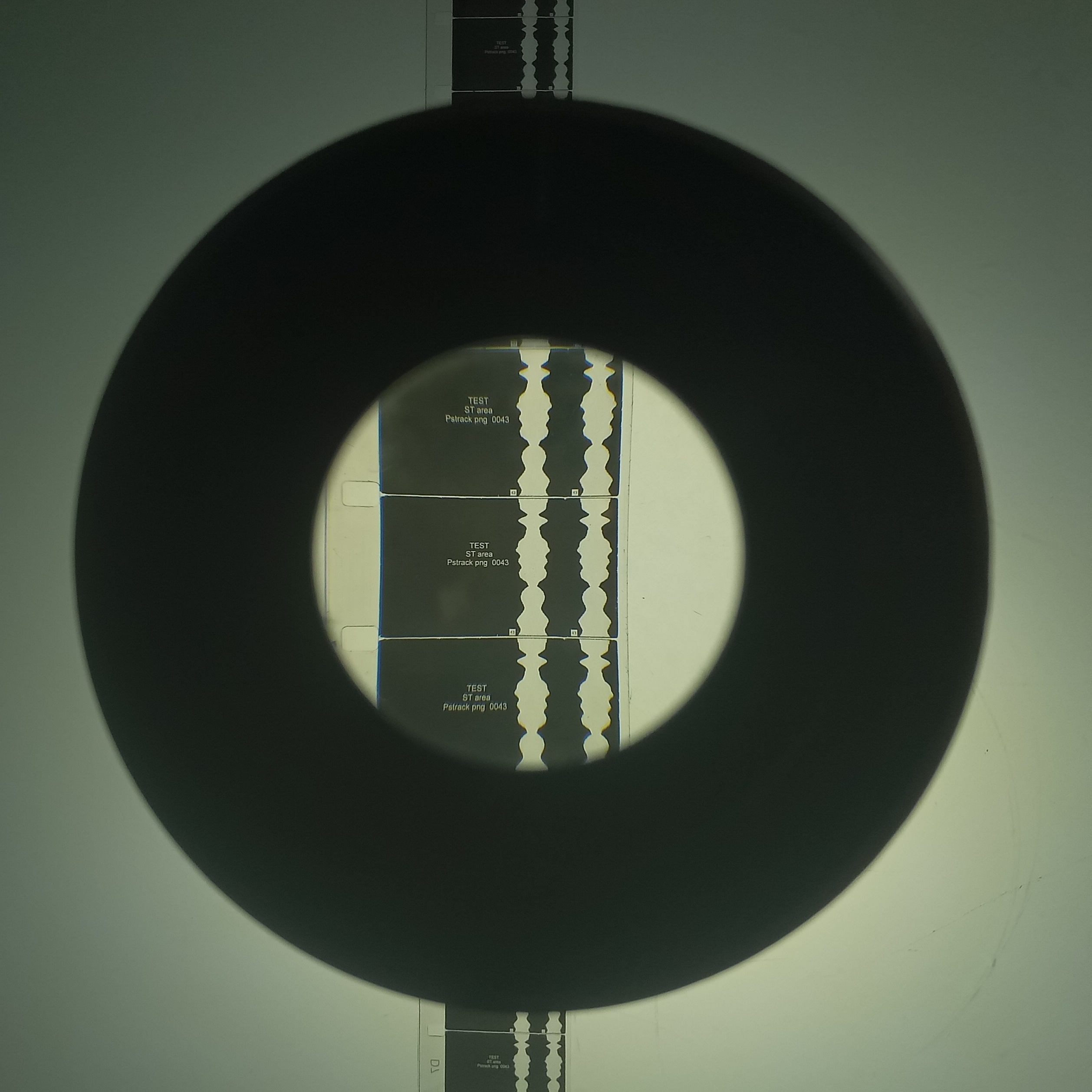
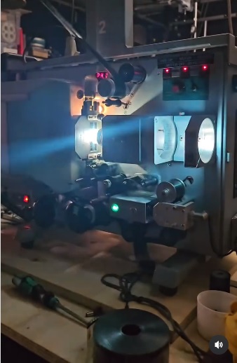
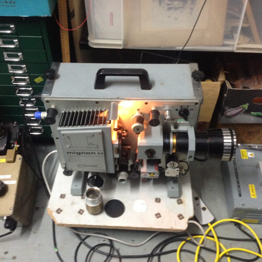
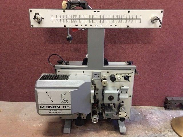
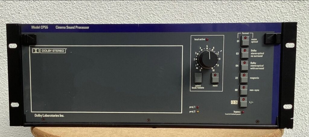
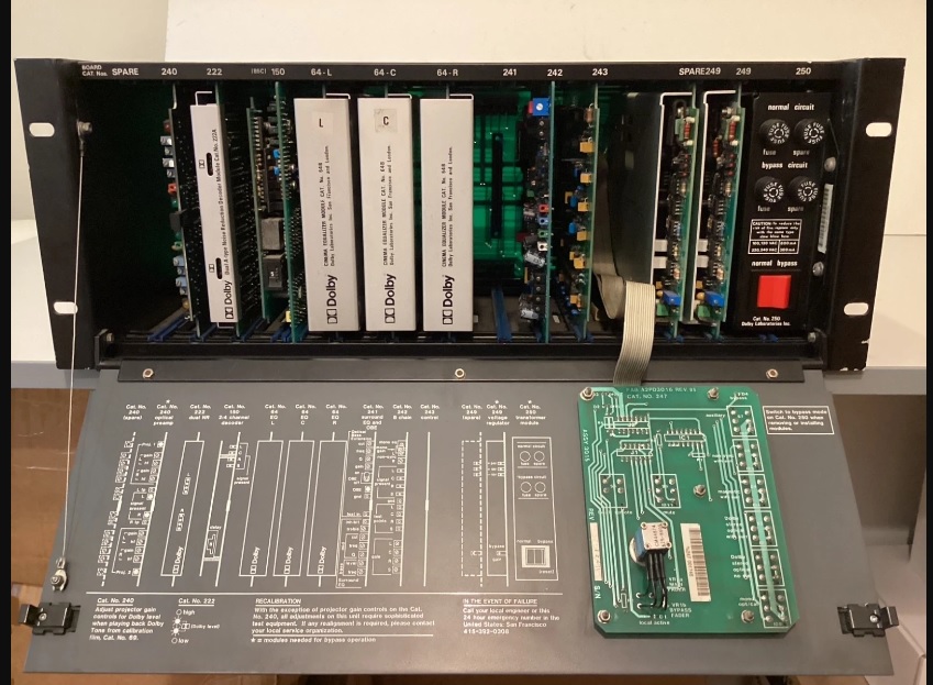
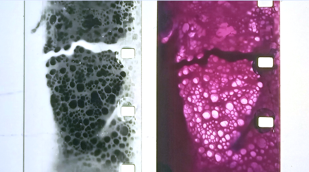
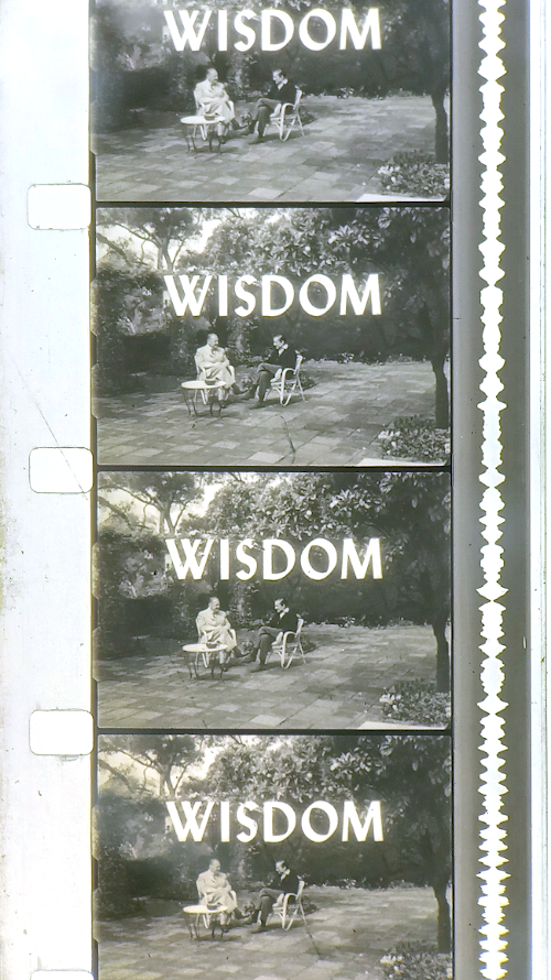 Clip from found footage work that I am using a lot at the moment. A film about the British writer Somerset Maugham where he utters the line to the interviewer at one point “I draw the line at incest”.
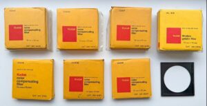
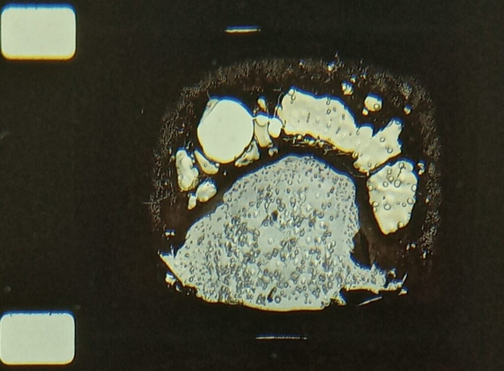


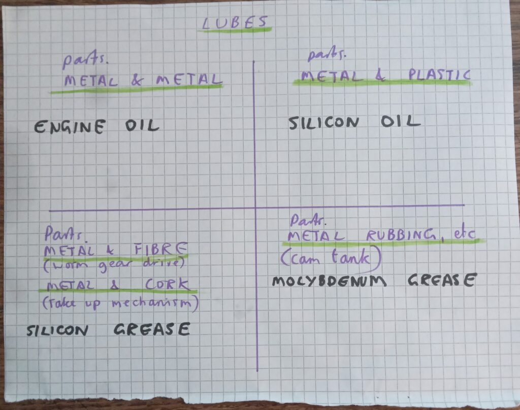
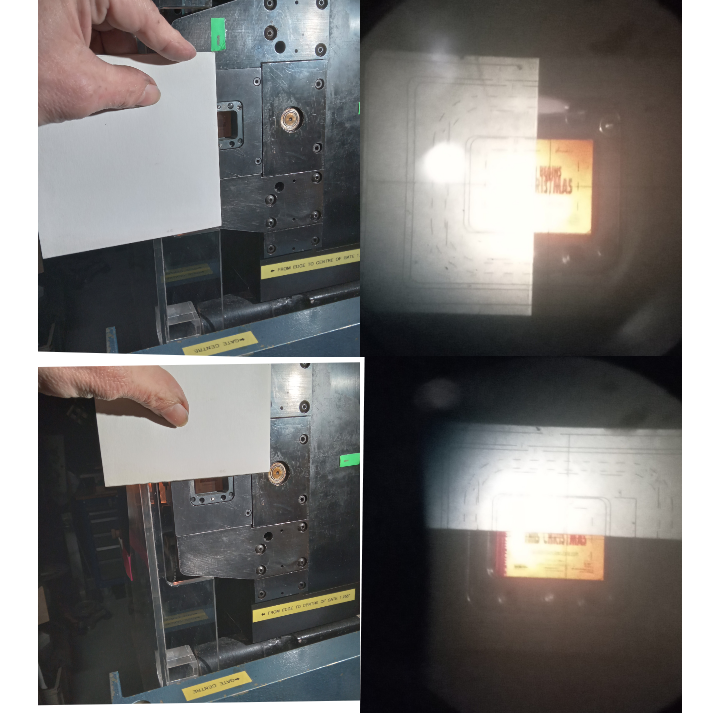

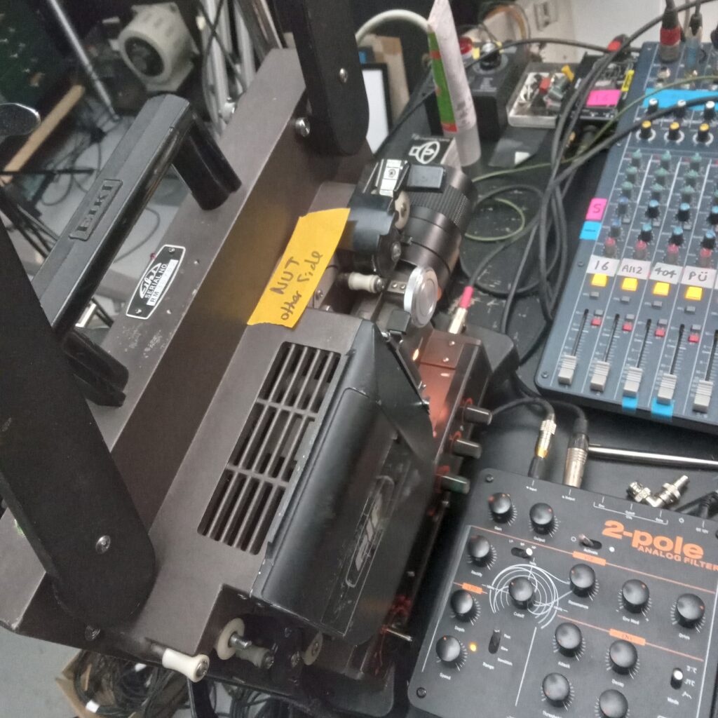
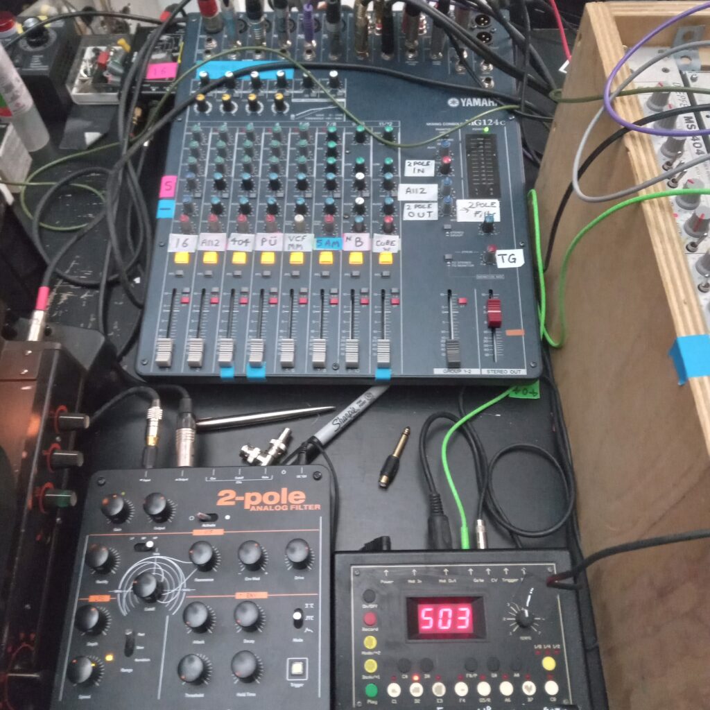
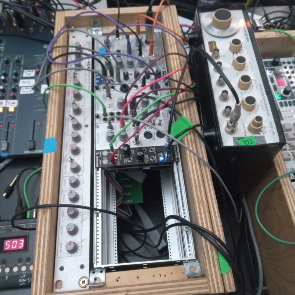
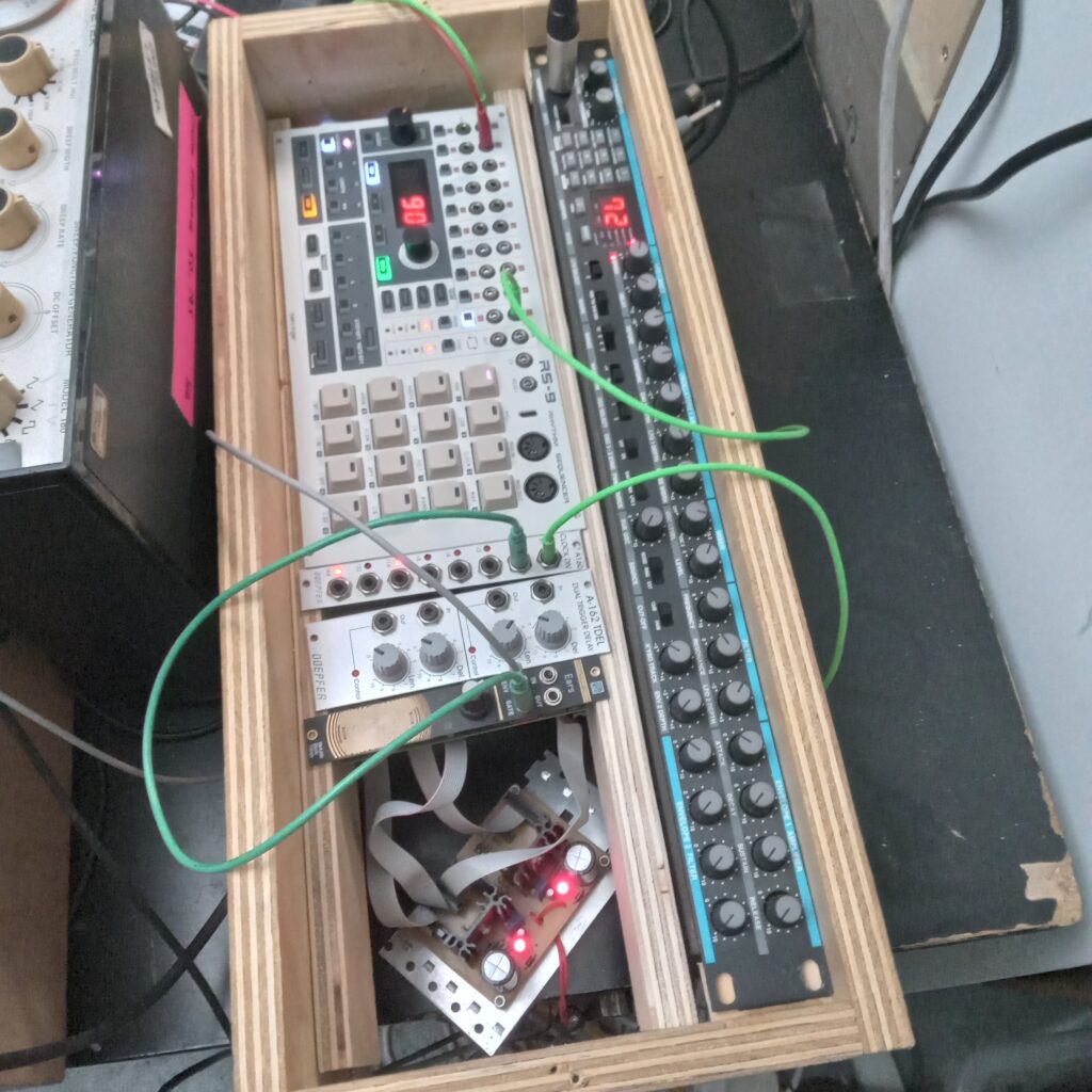
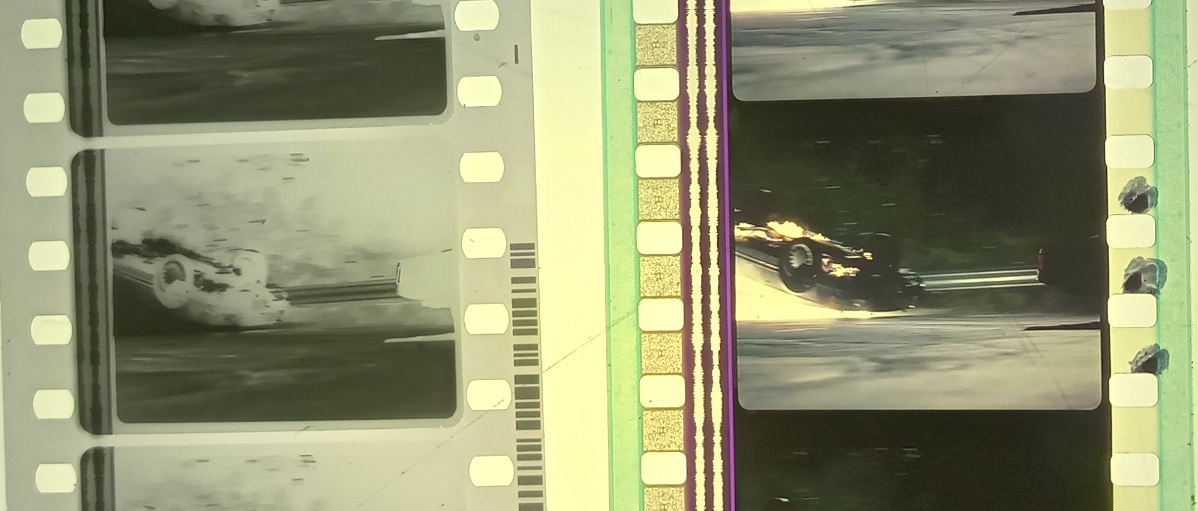
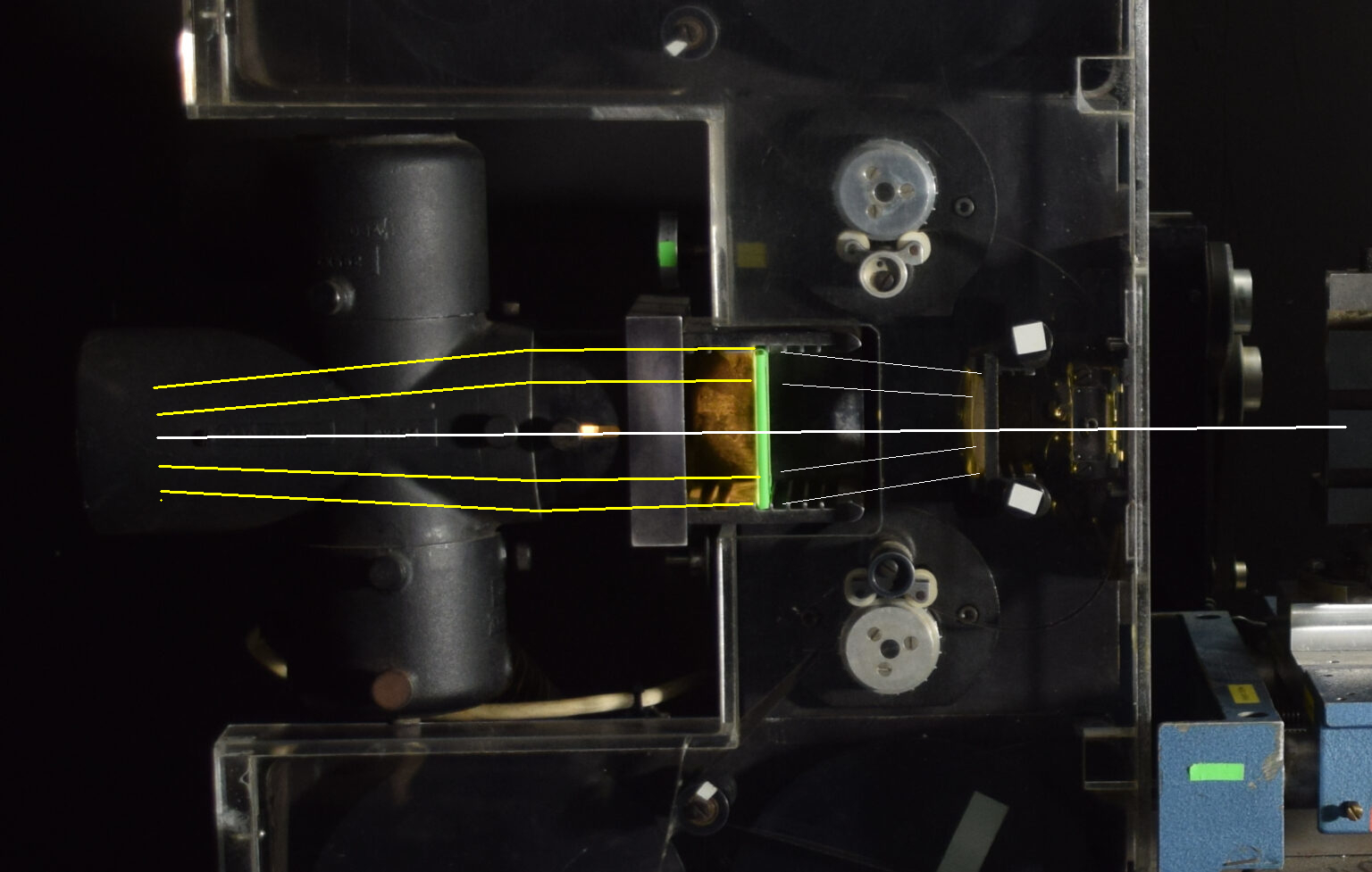

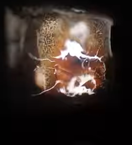
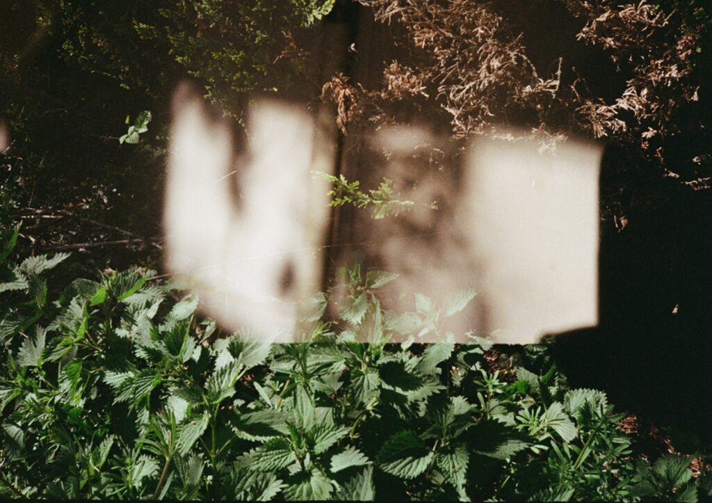
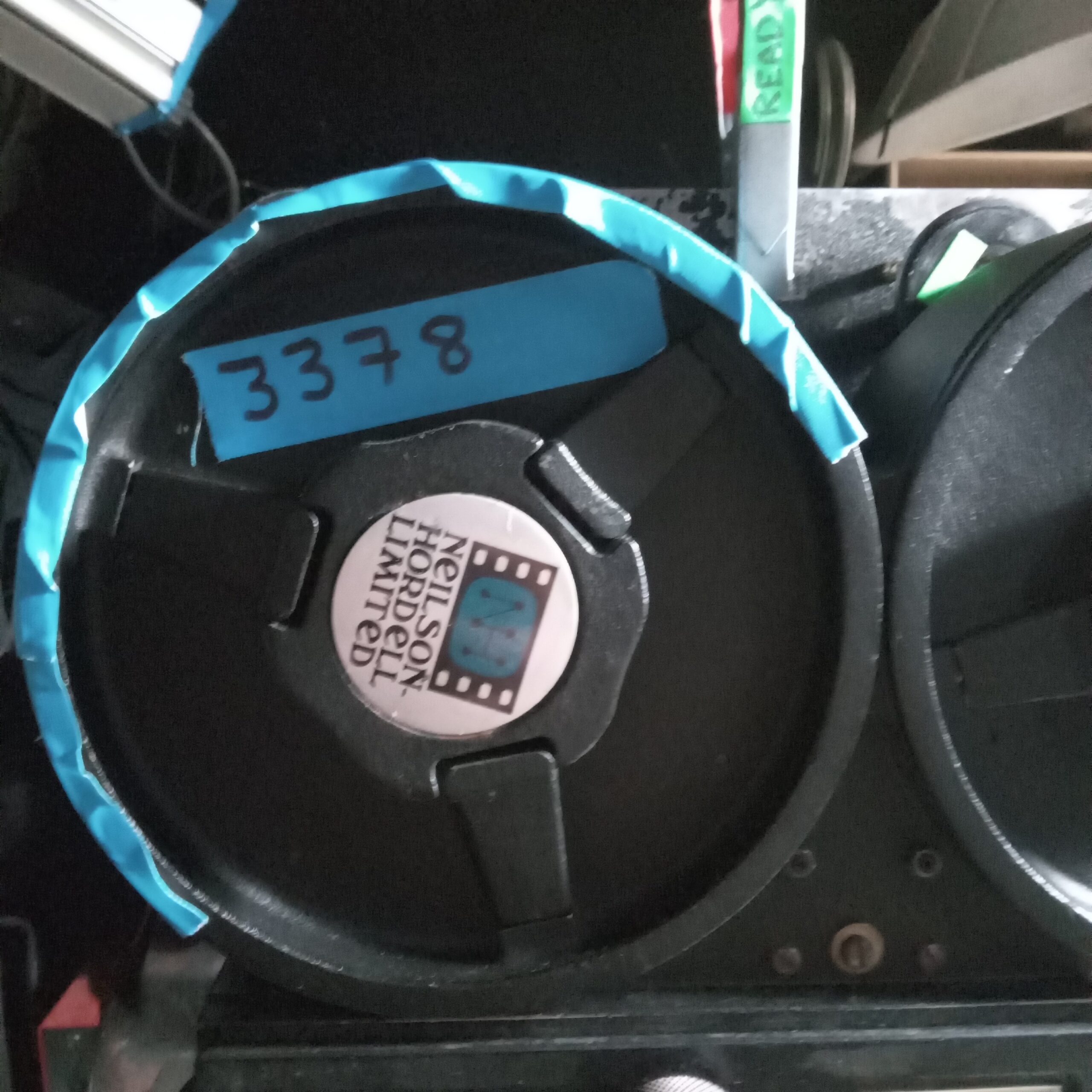
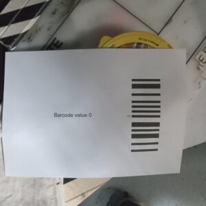

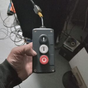
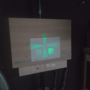
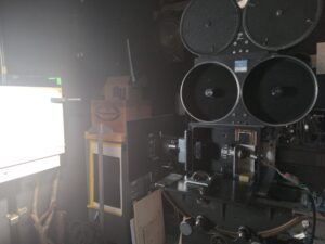
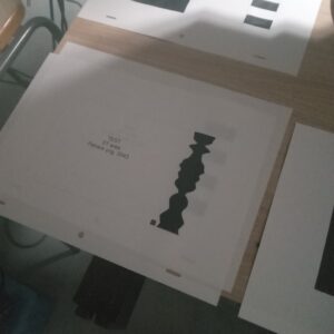
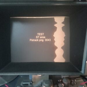
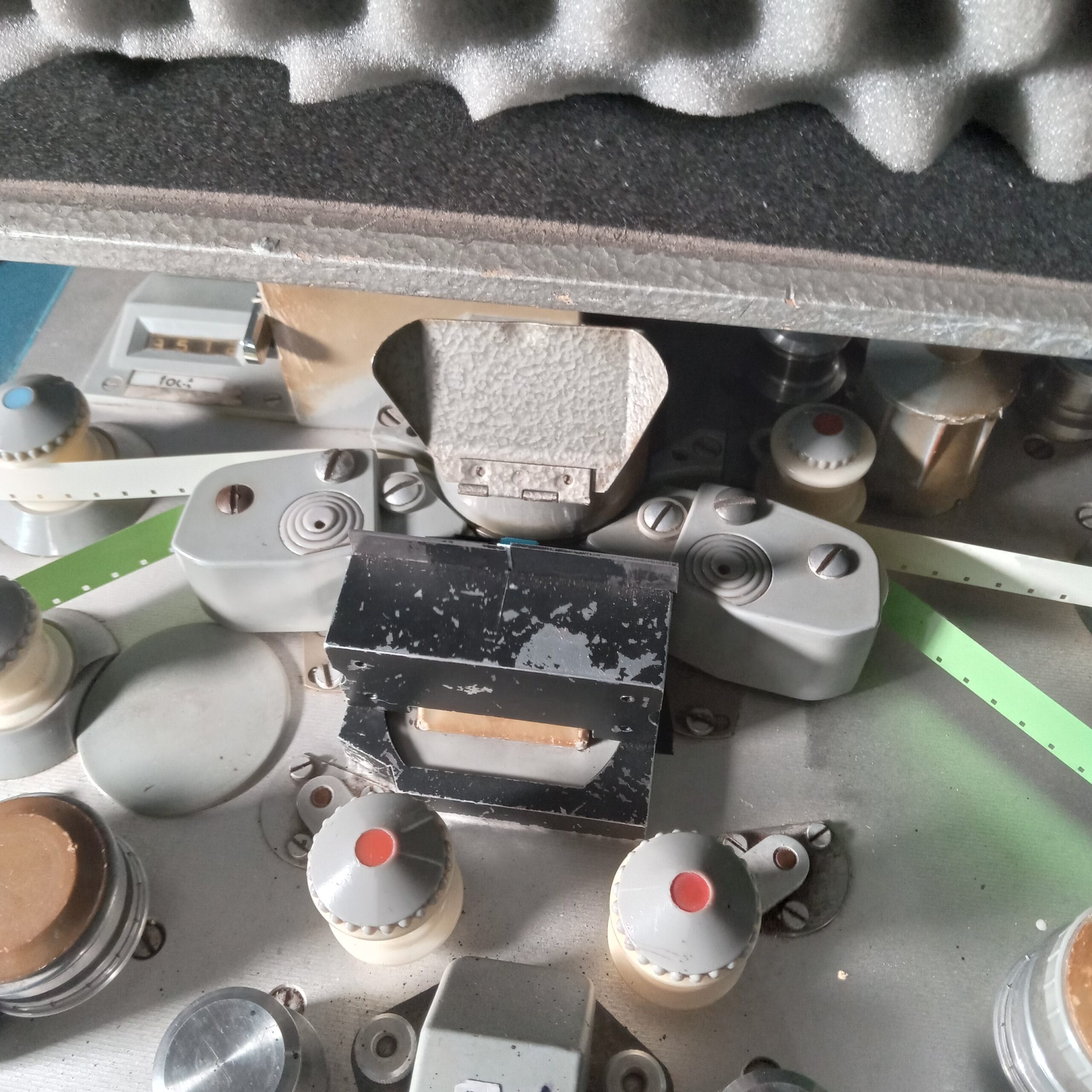
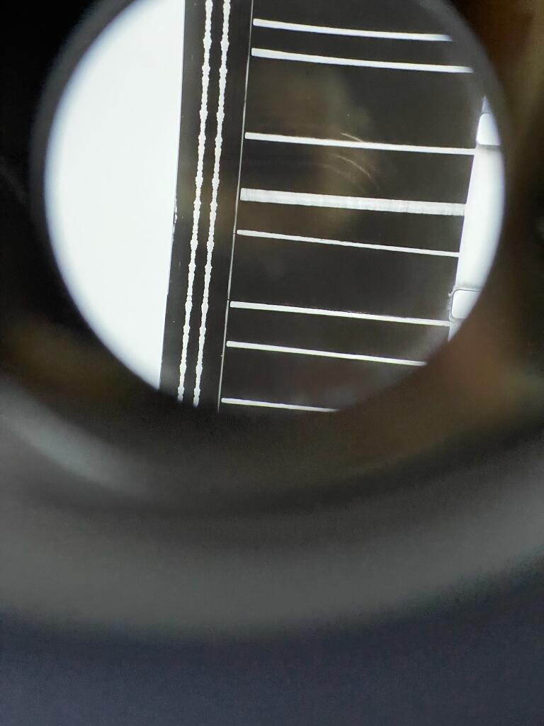
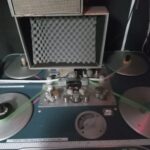

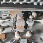
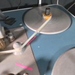
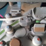
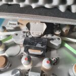
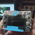
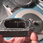
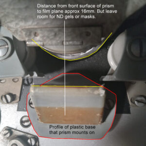
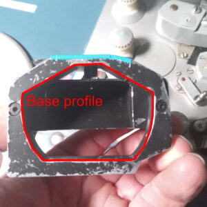
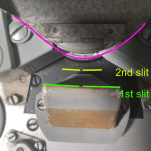
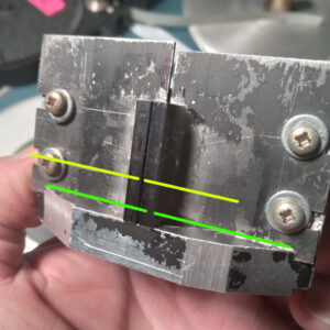
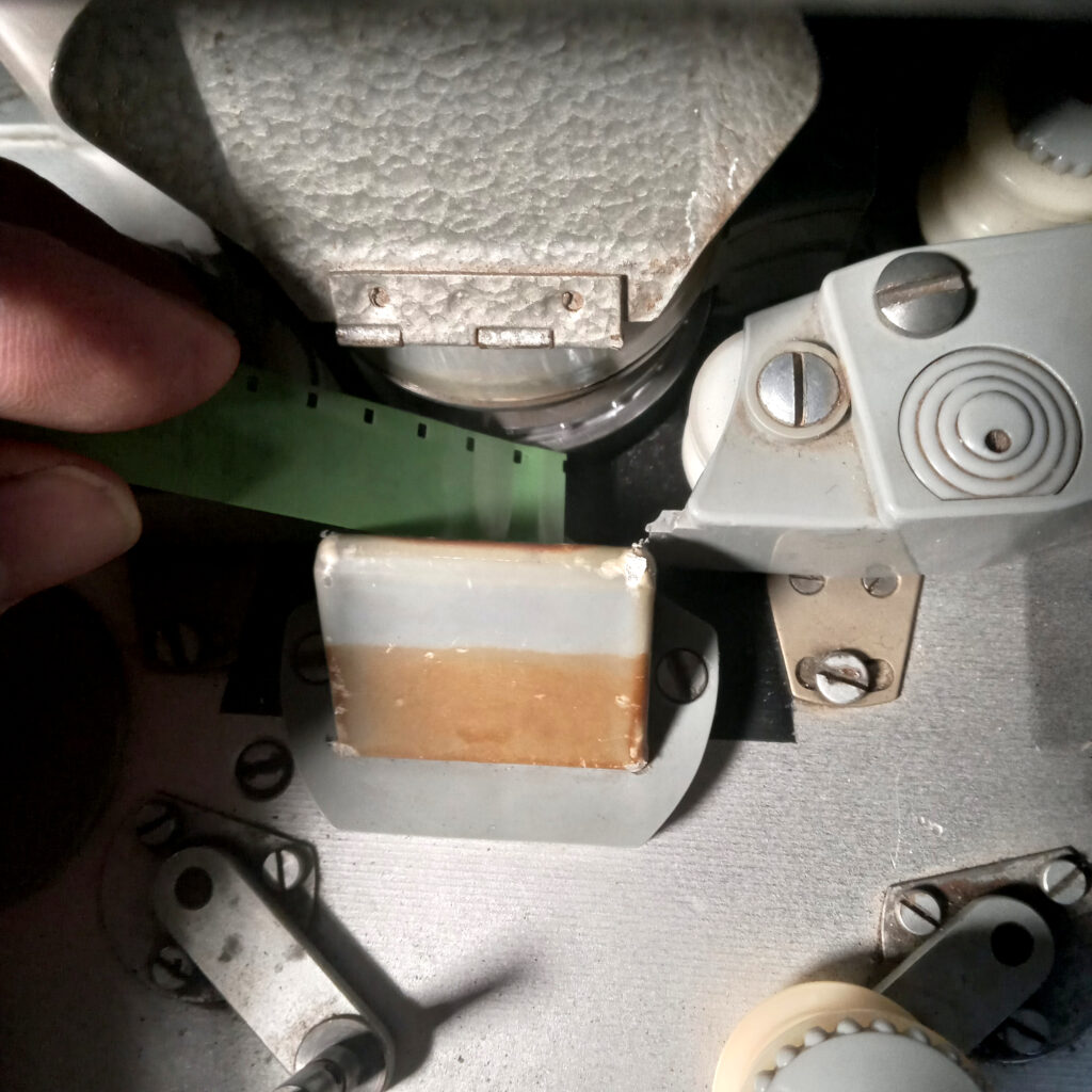 What you want to achieve is a slit about 1mm wide, as absolutely parallel as you can, that is as near to the film plane as possible but with enough room to be able to tape ND gel onto the front. 3D printing might work, etc. The quality of a contact print depends on the nature of the OG and you will almost surely need to make several tests until you get the ND value right.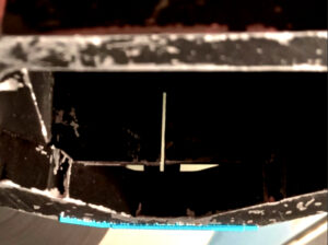
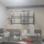
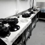
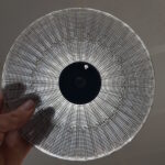
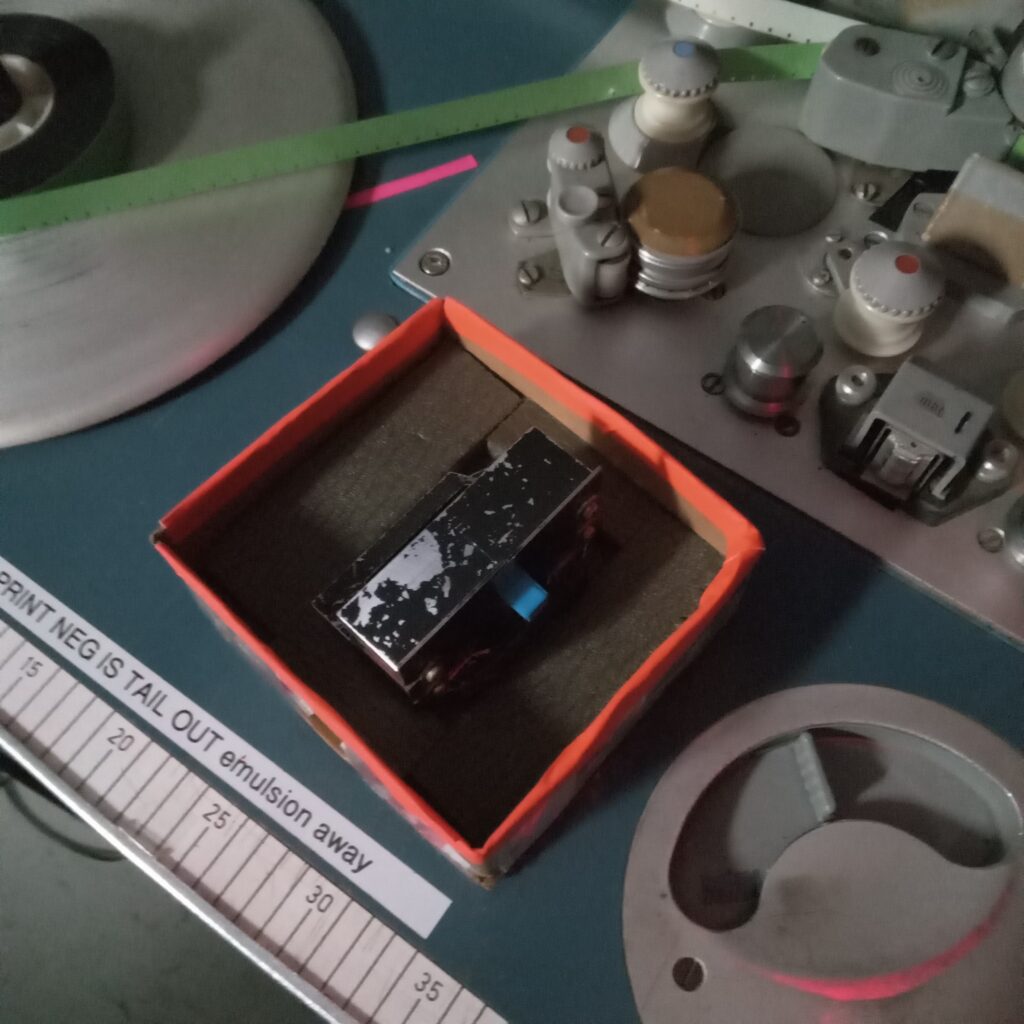
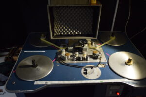
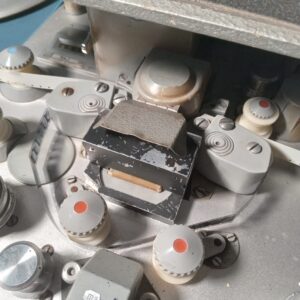
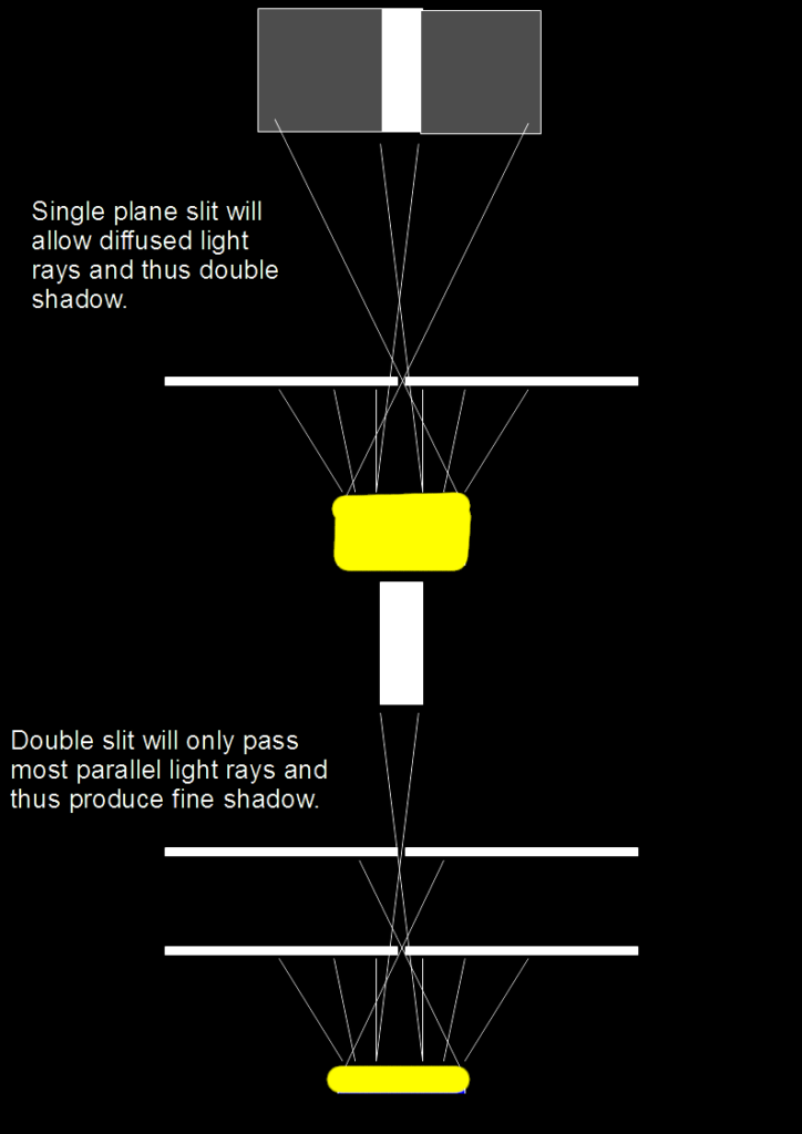
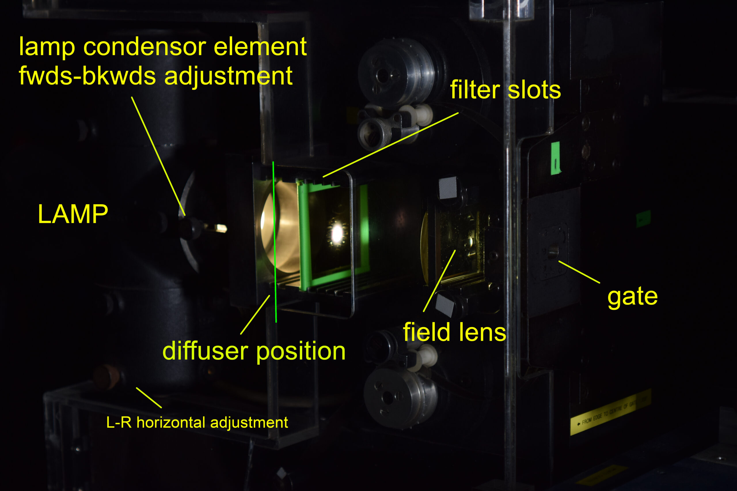
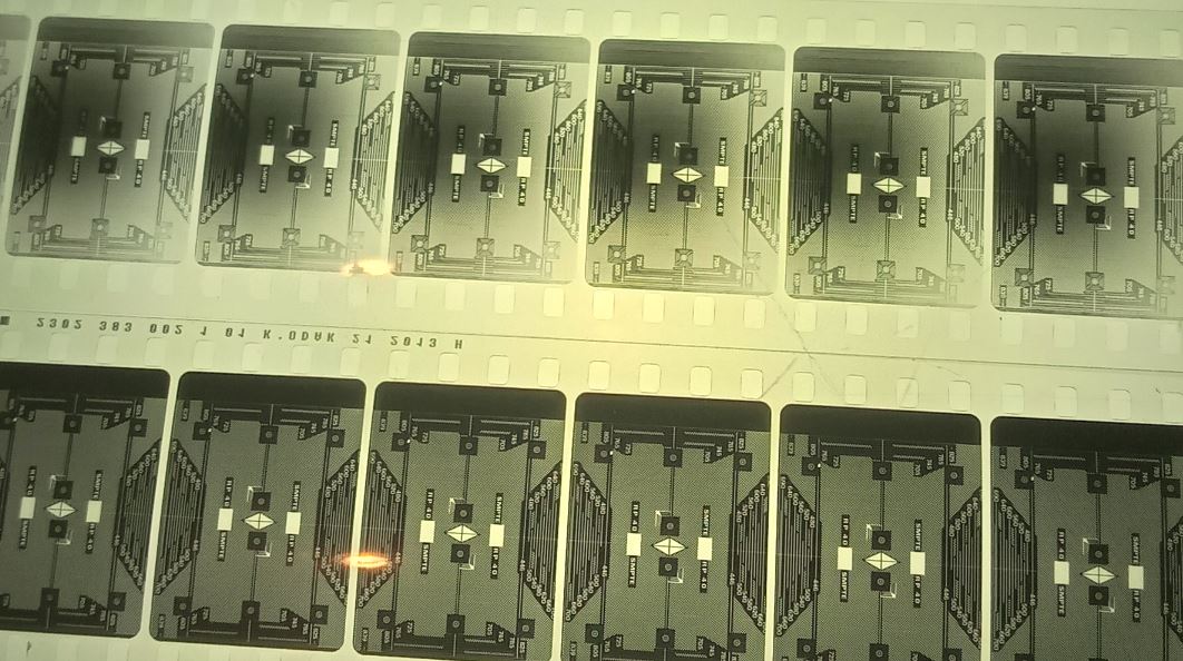
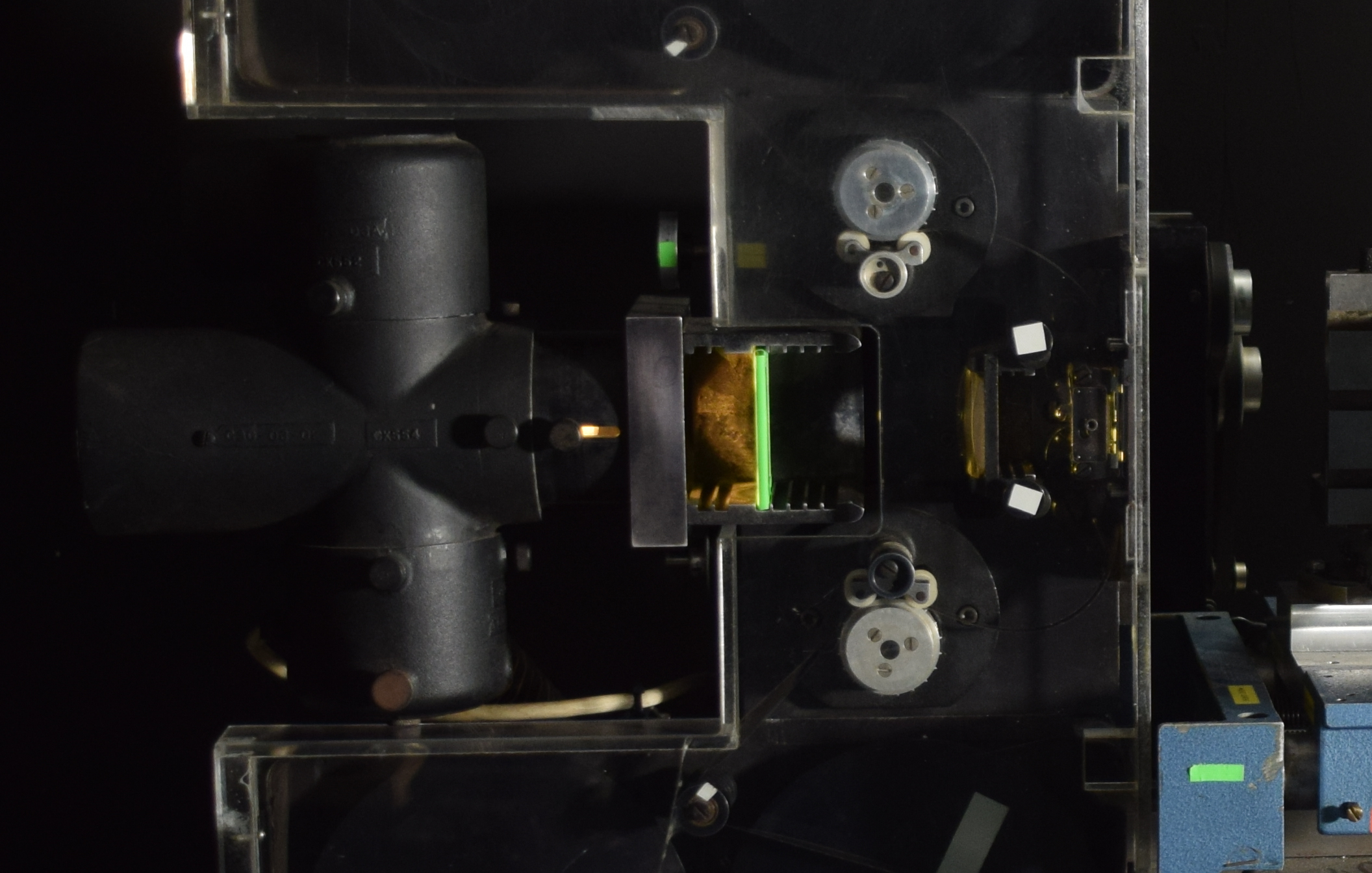
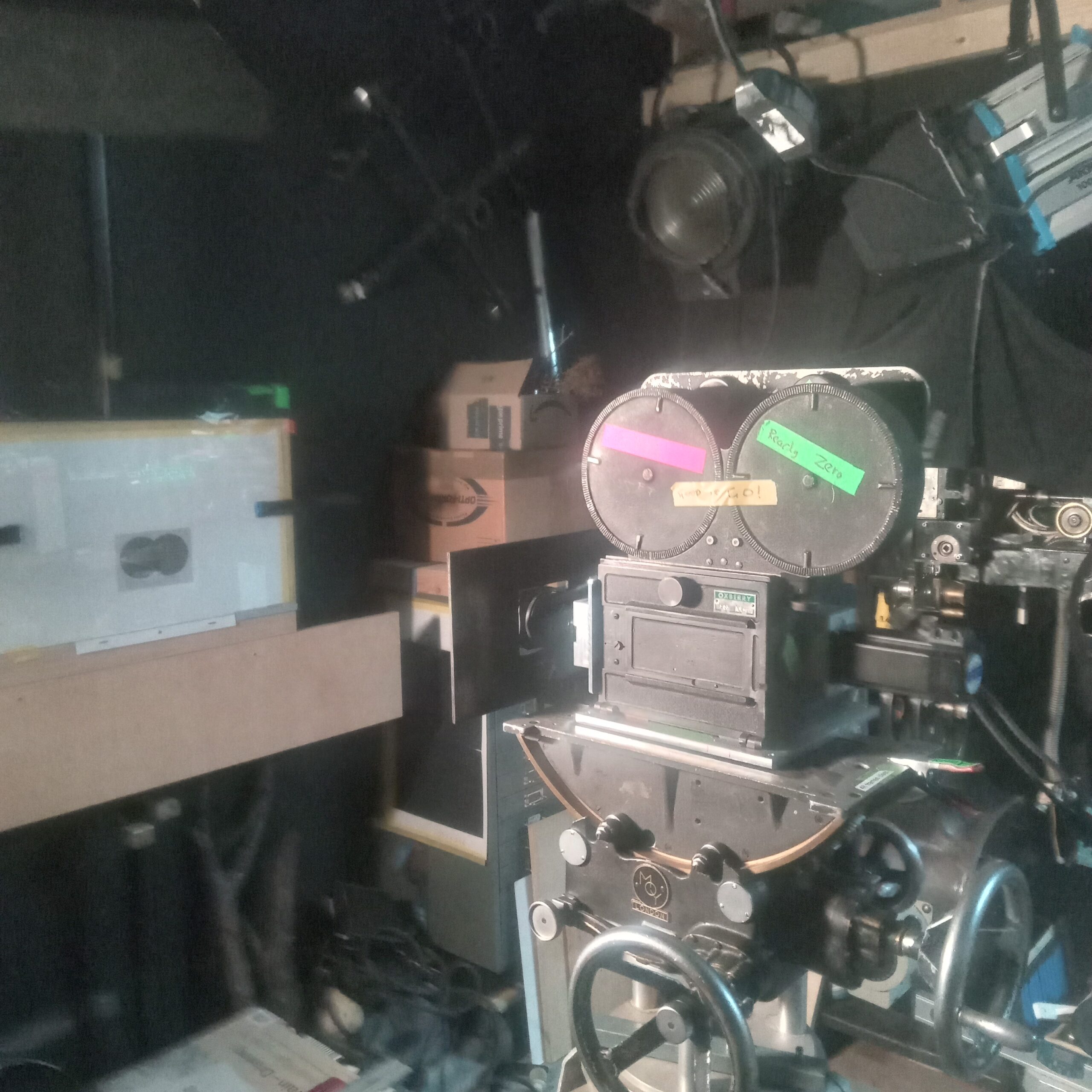
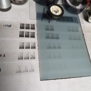
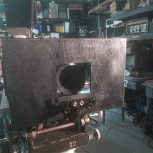
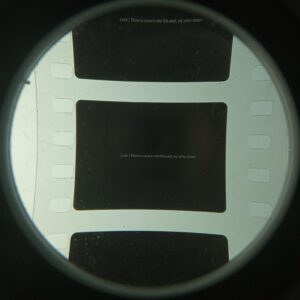
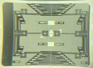
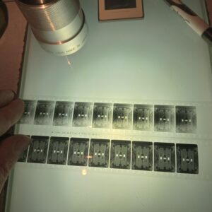
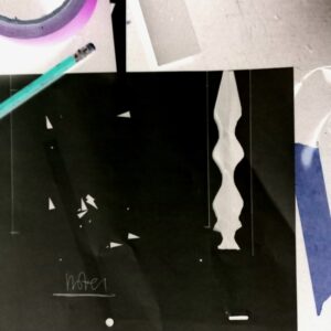
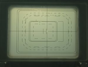
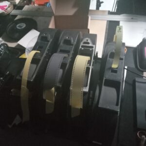
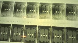
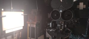
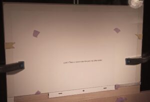

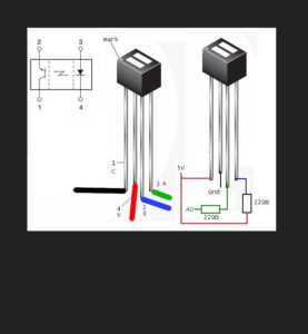
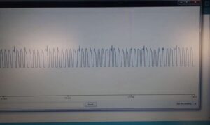
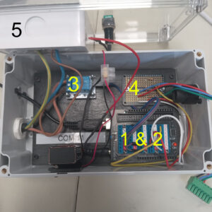
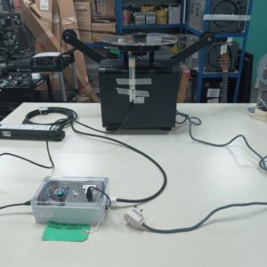
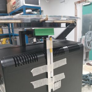
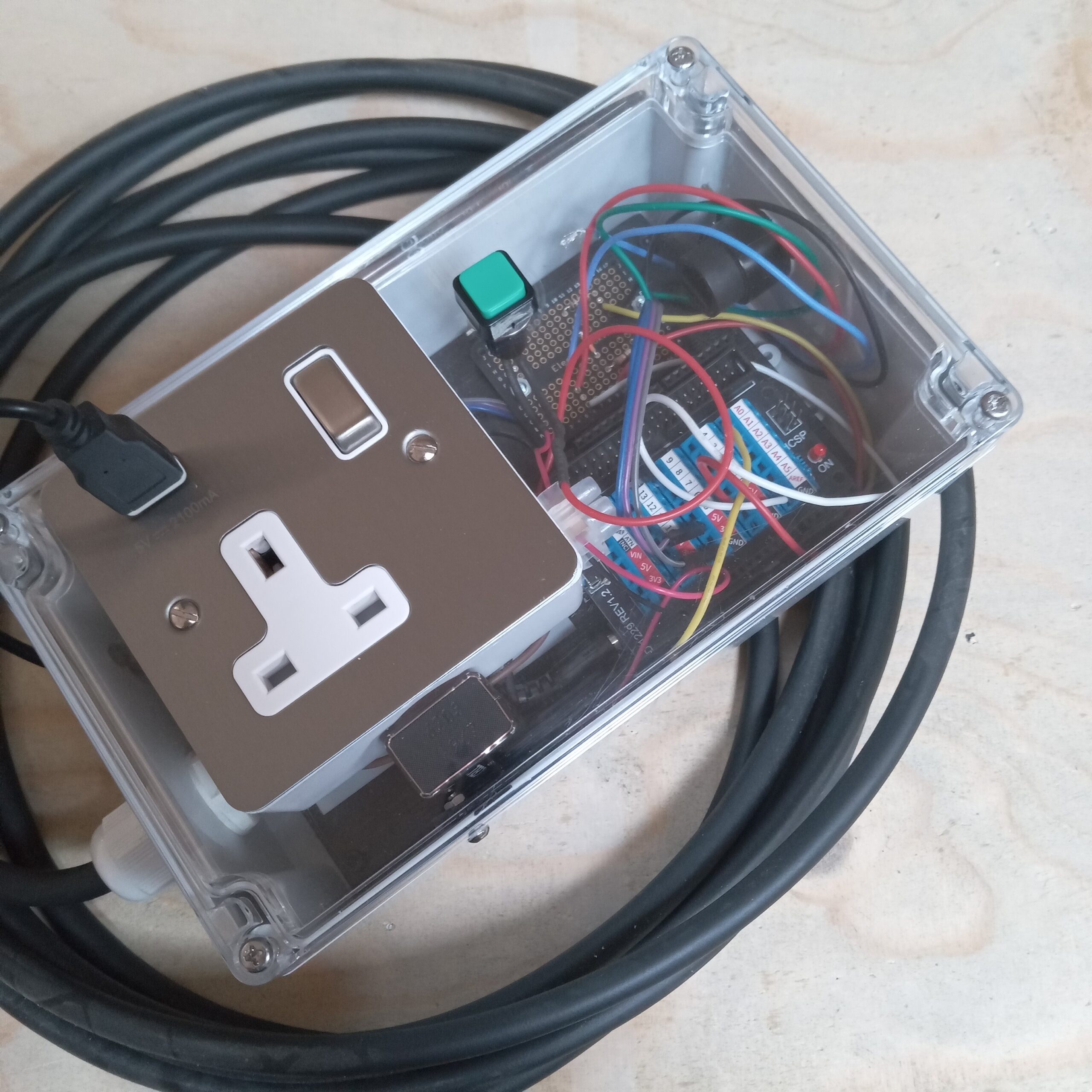
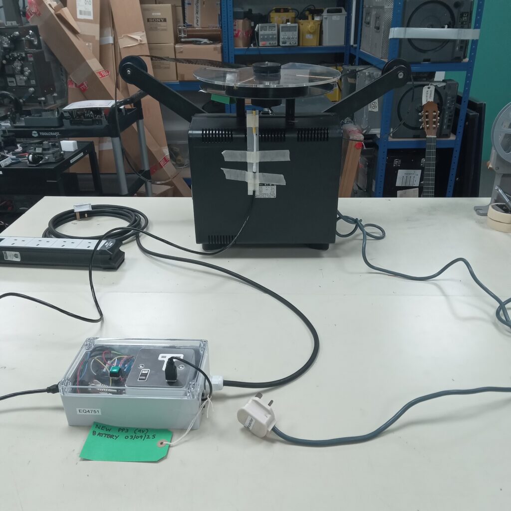
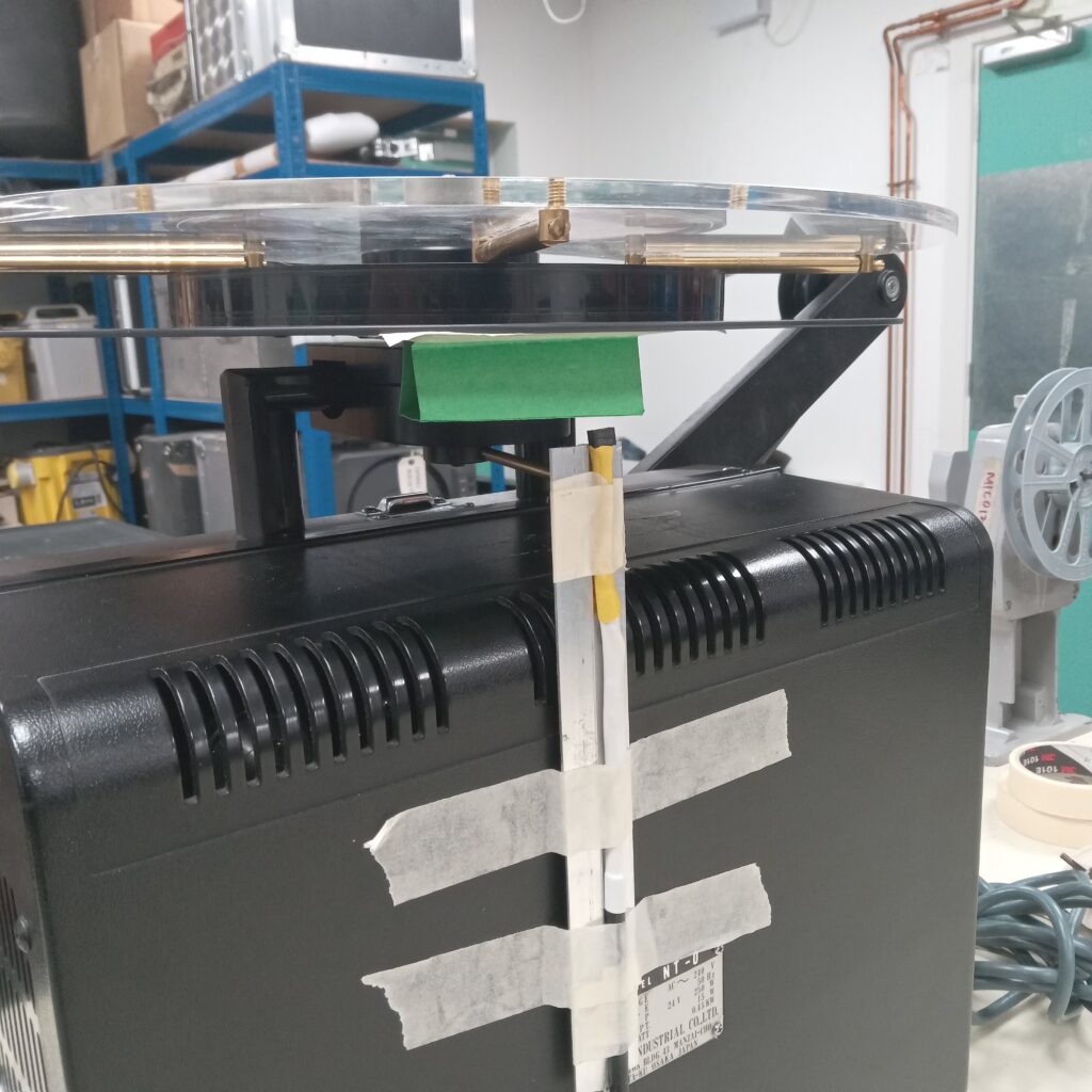
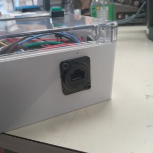
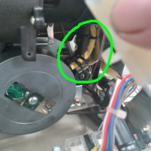
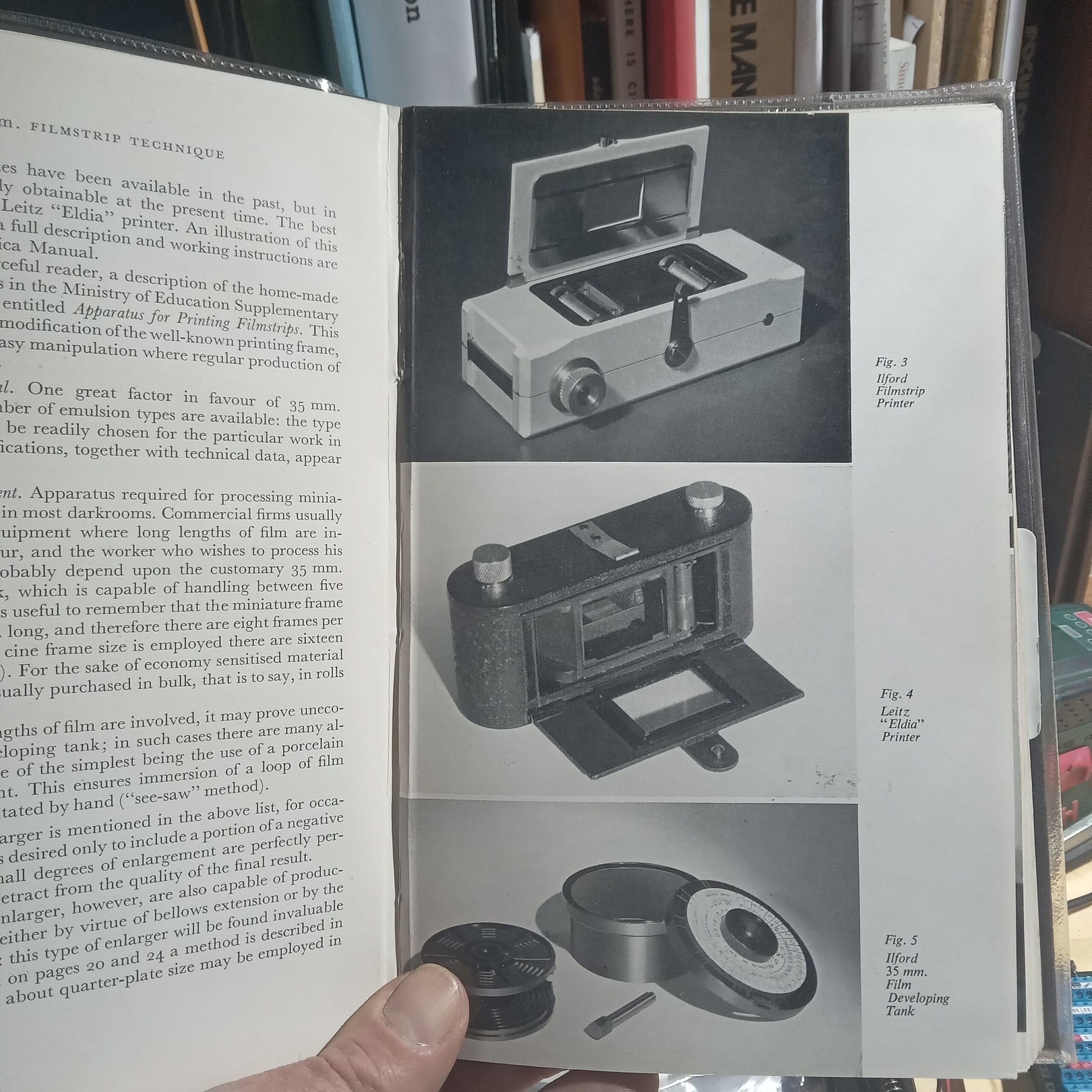
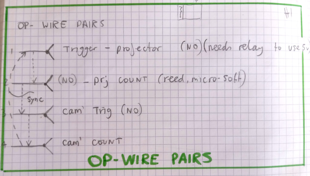
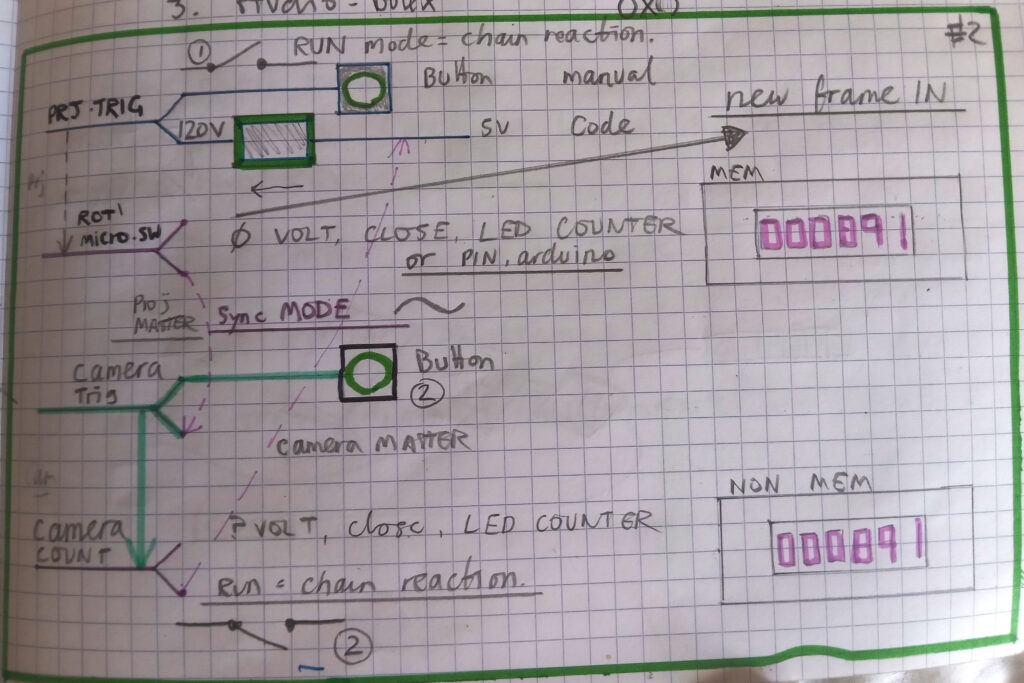
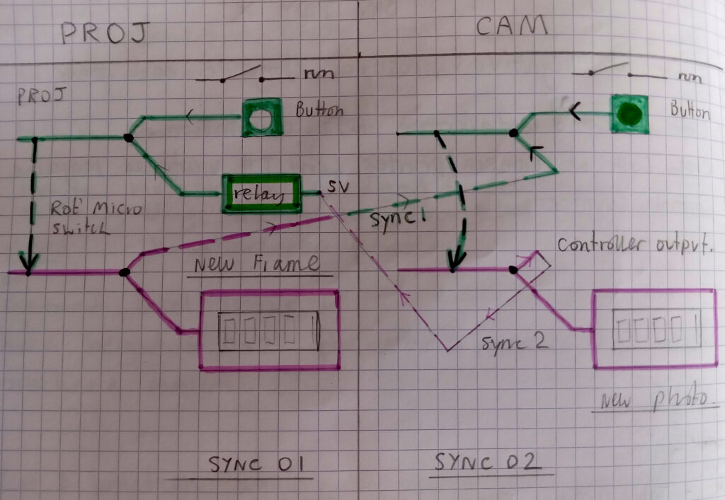
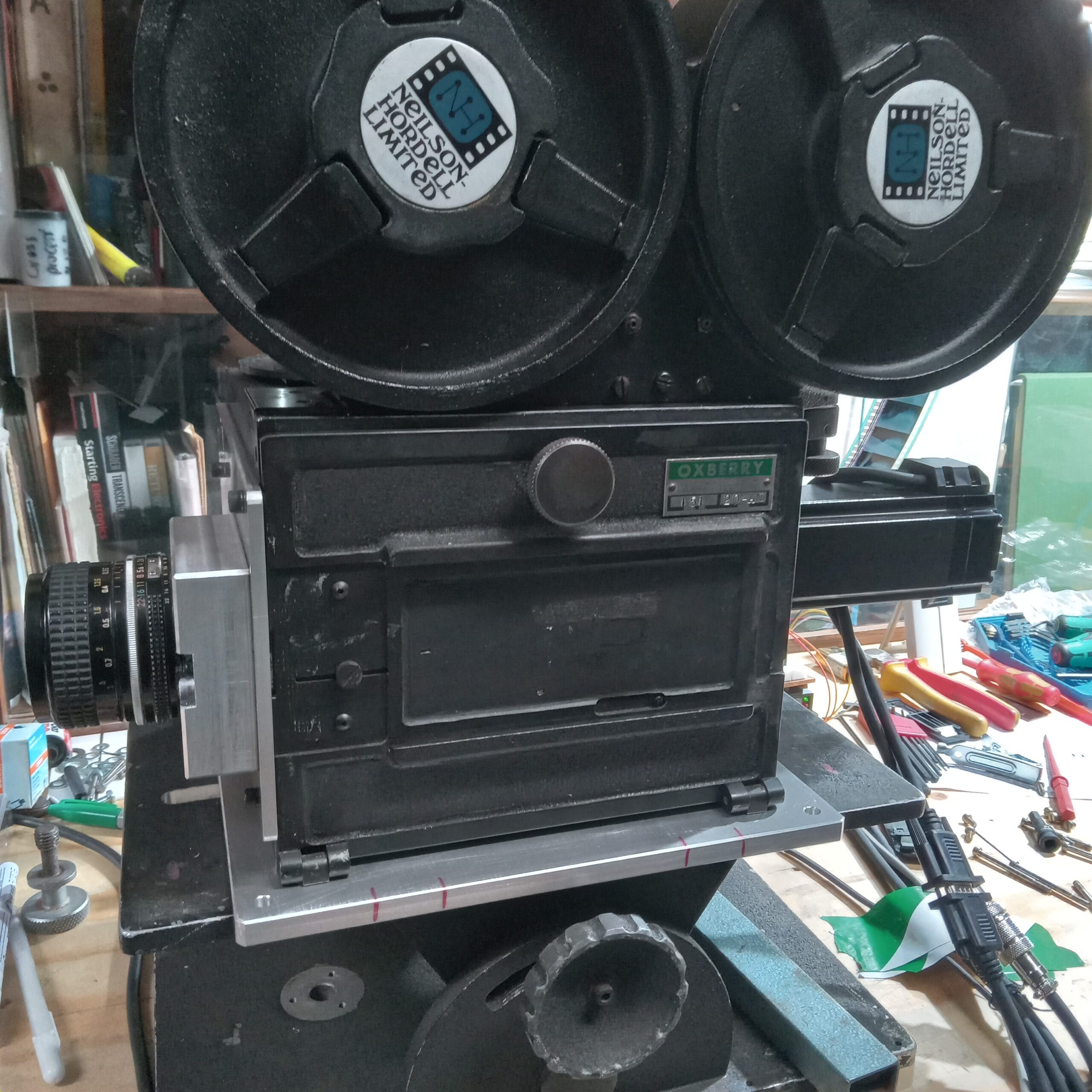
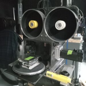
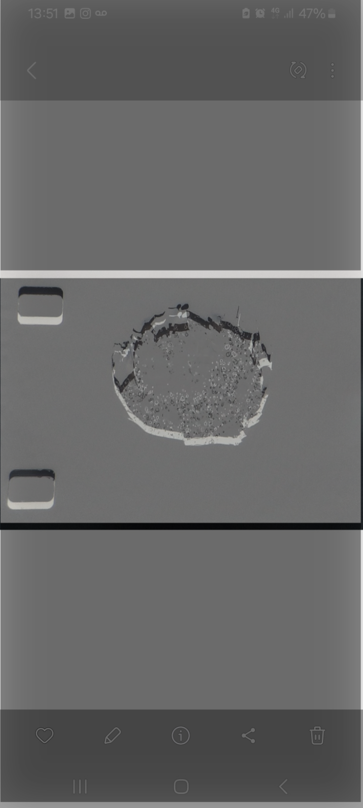
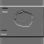
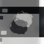
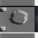
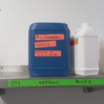
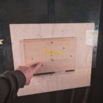
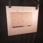
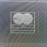
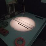
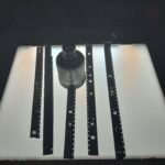
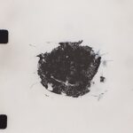
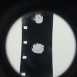
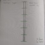
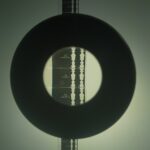
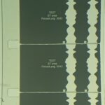
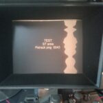
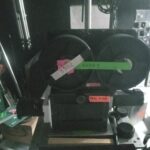
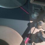
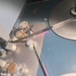
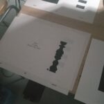
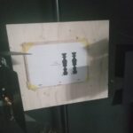
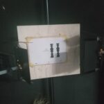
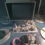
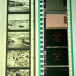
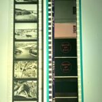
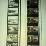
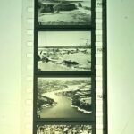
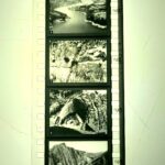
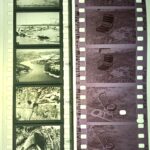
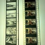
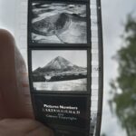













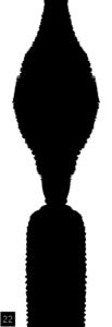









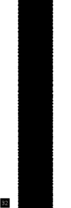







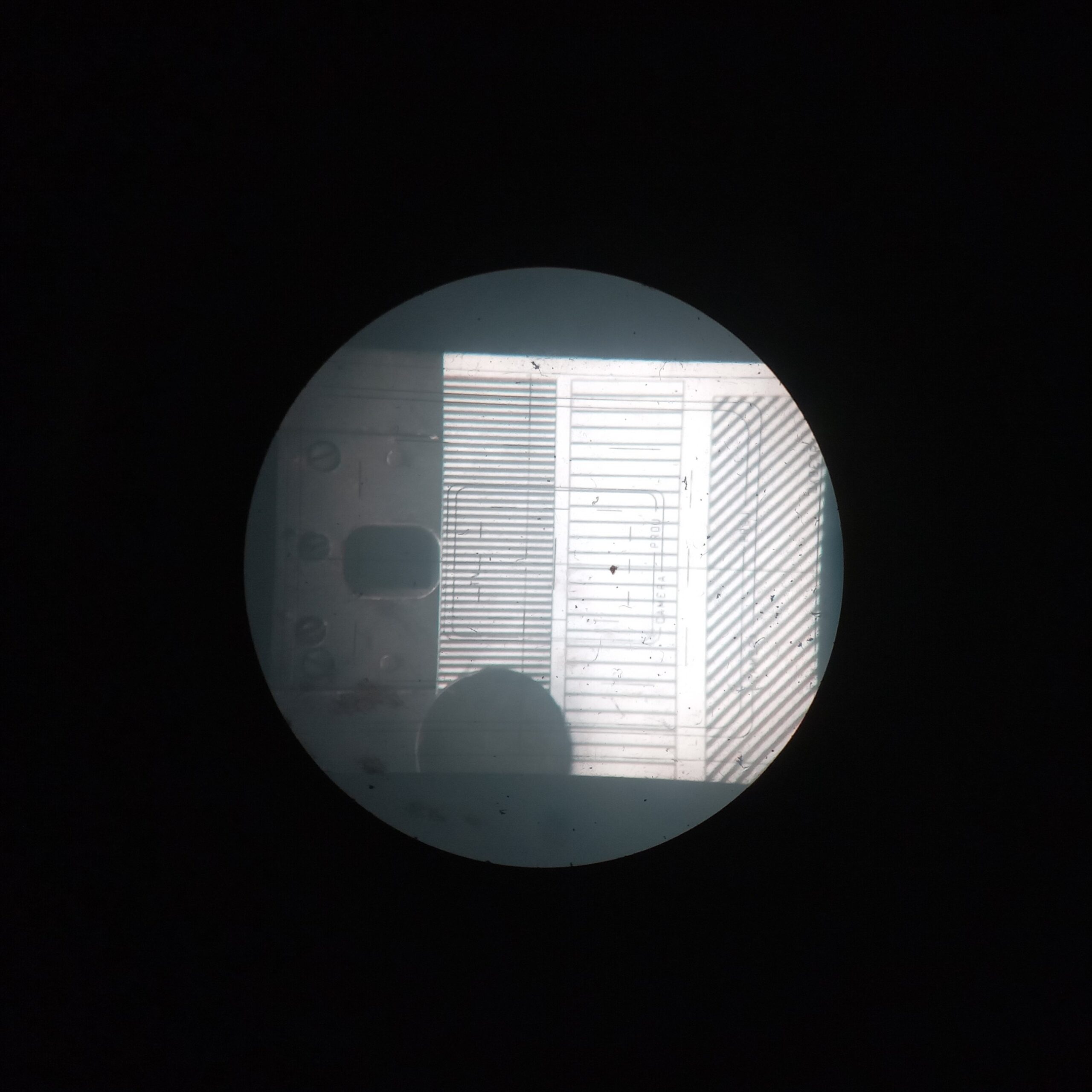
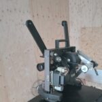
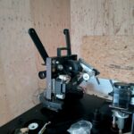
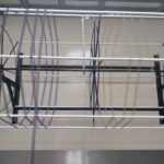
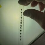
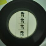
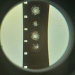
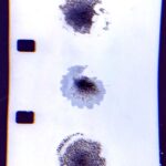
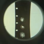
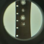

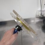
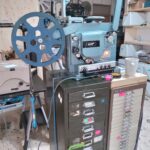
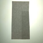
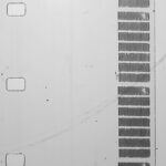
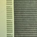
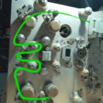
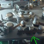
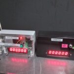
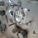
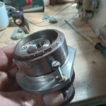
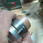
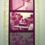
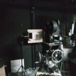
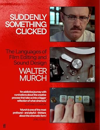
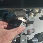
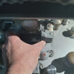
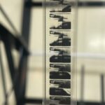
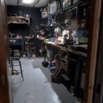
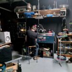
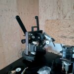
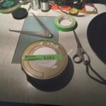
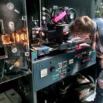
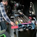
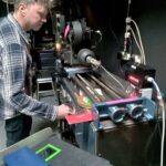
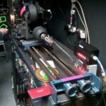
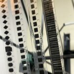
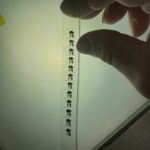
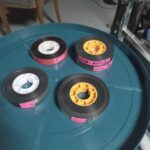
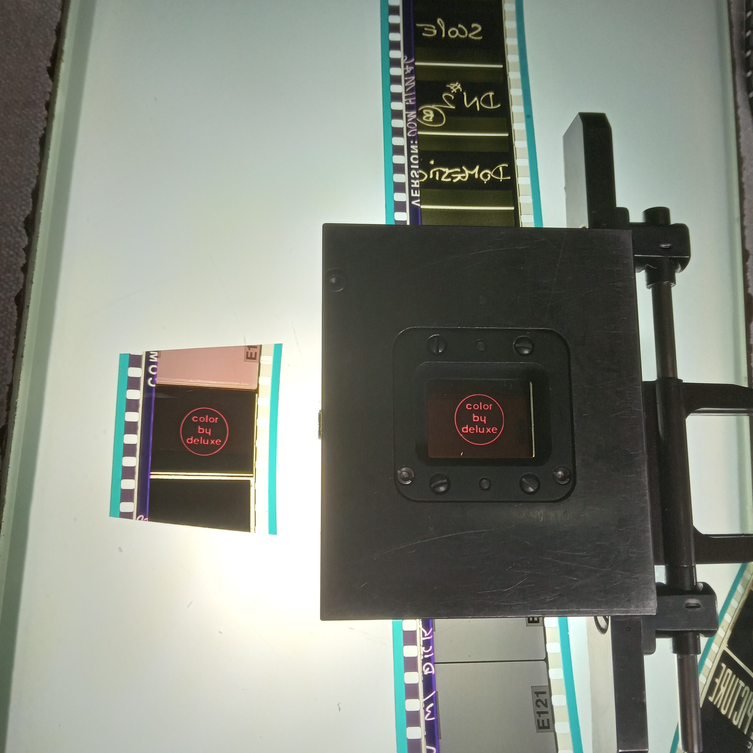
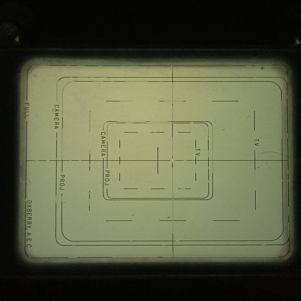
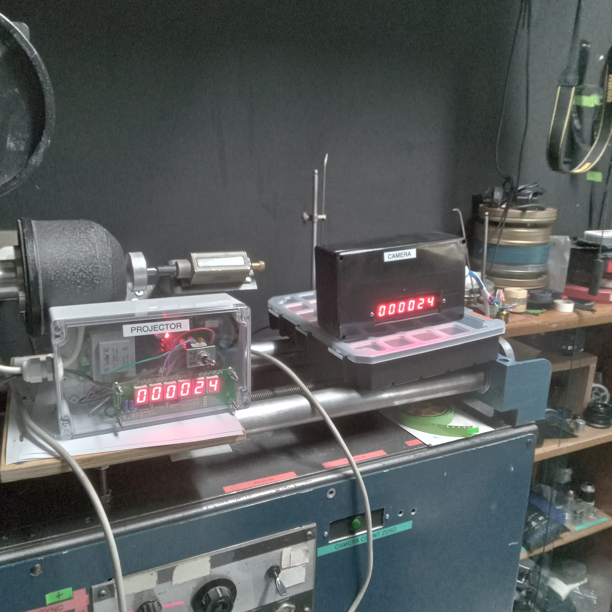
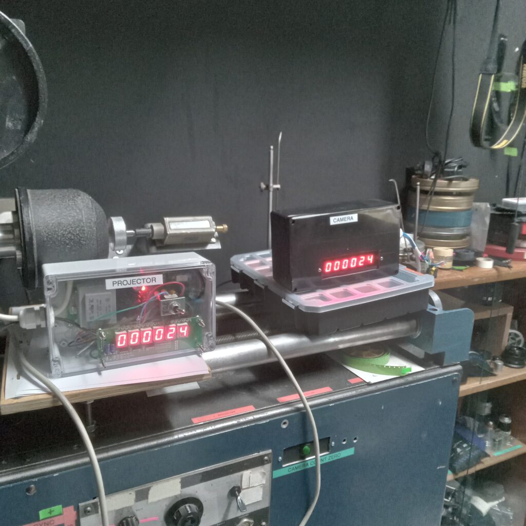
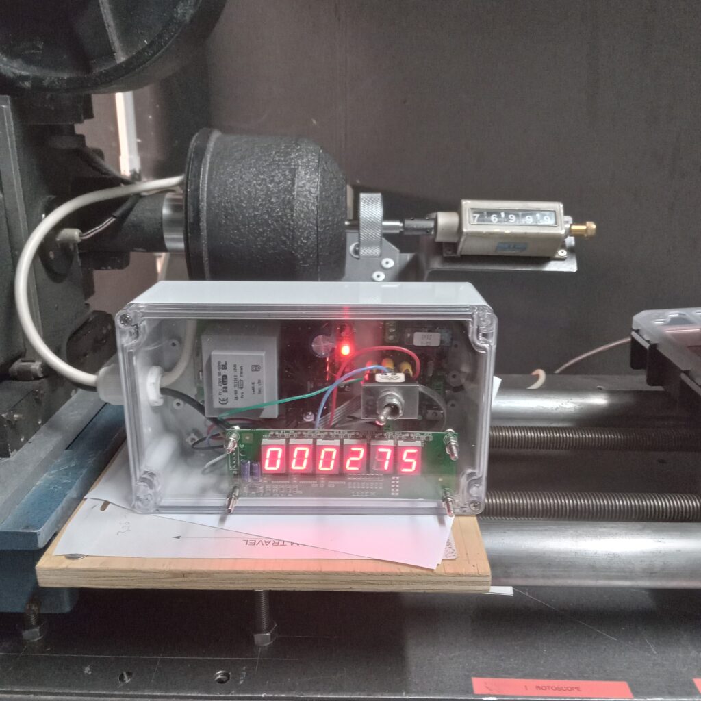
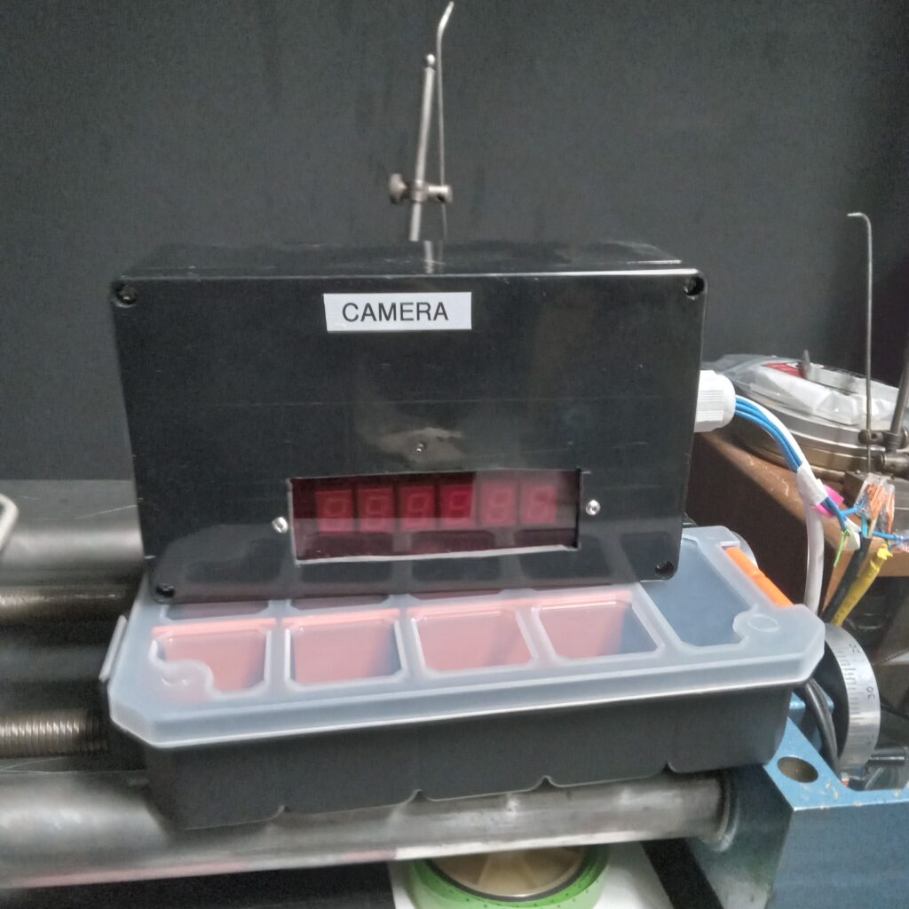
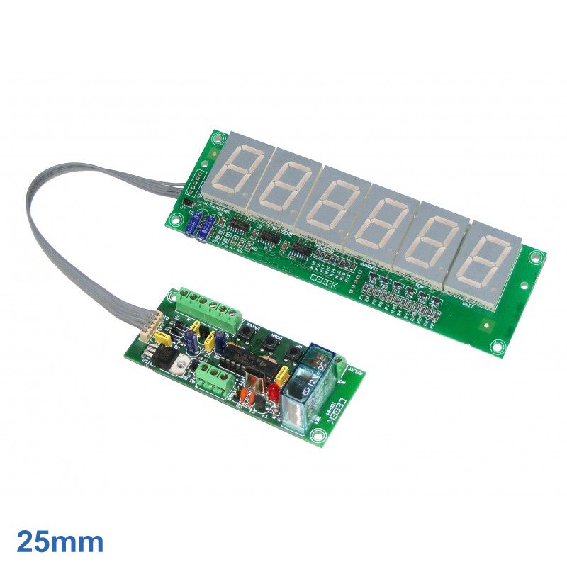
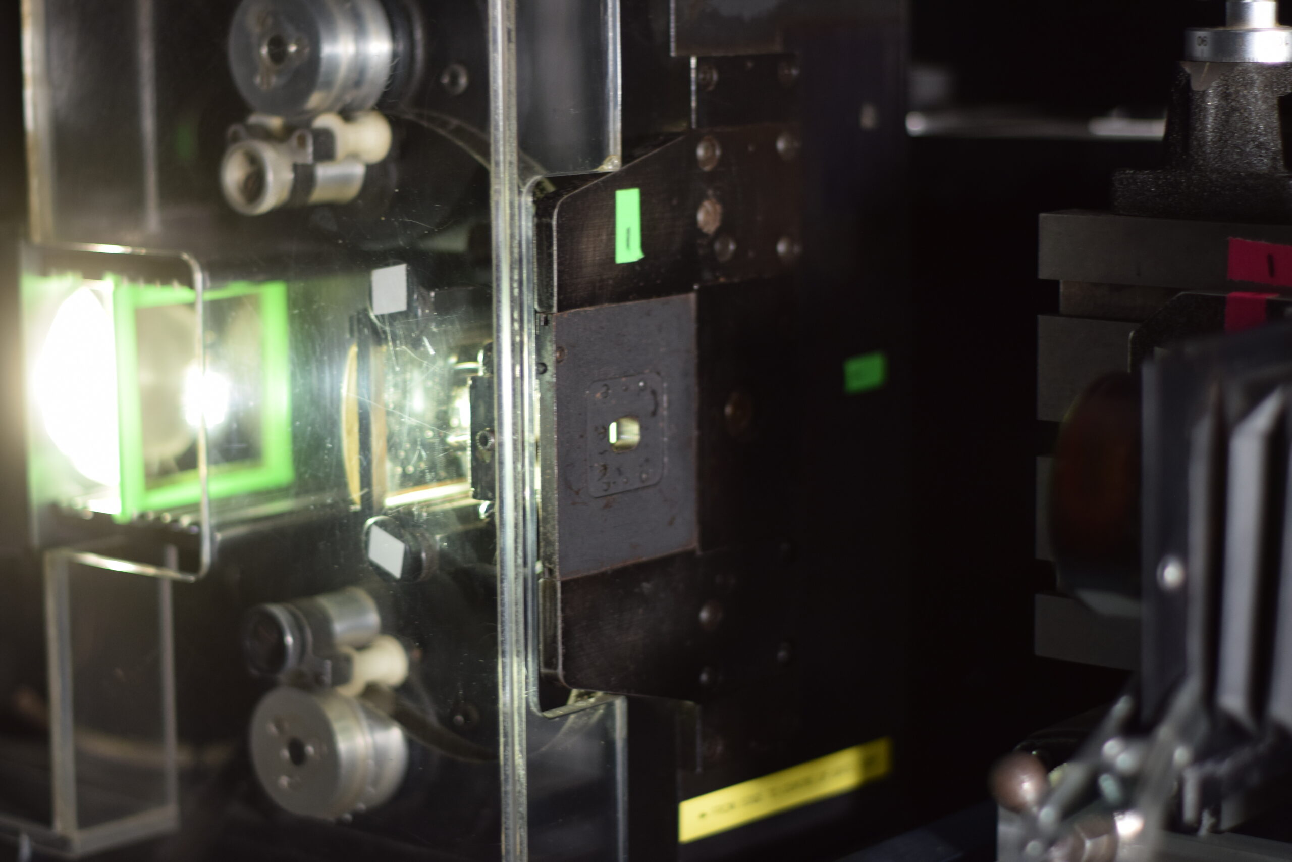
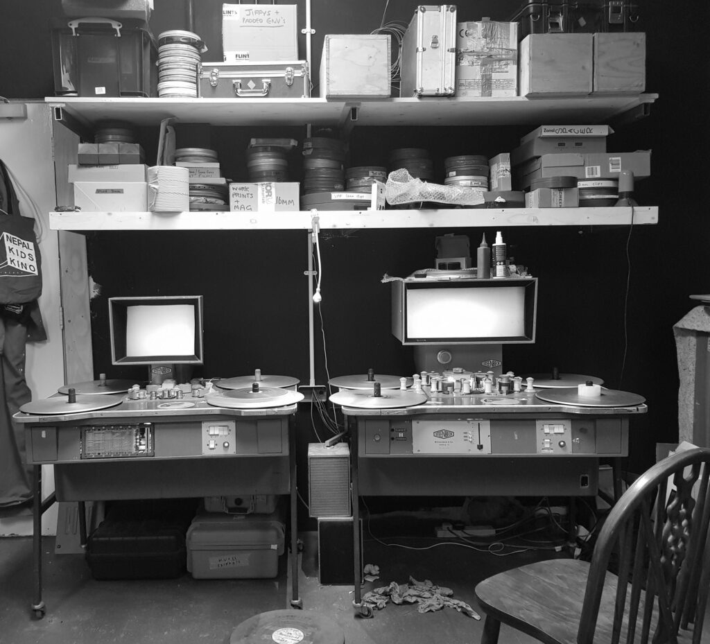
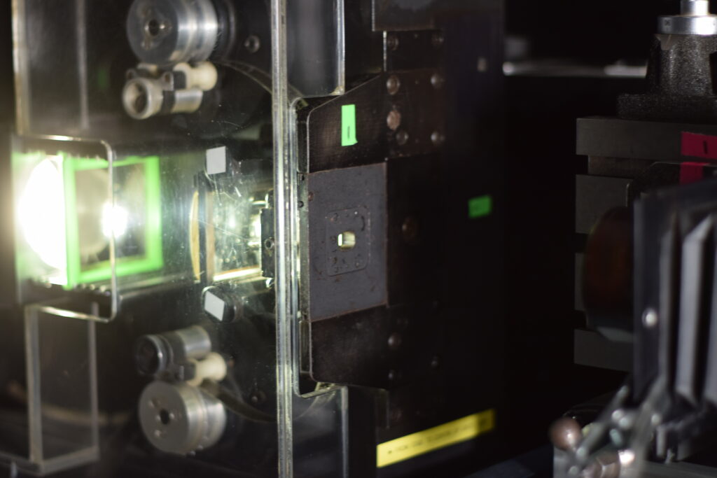
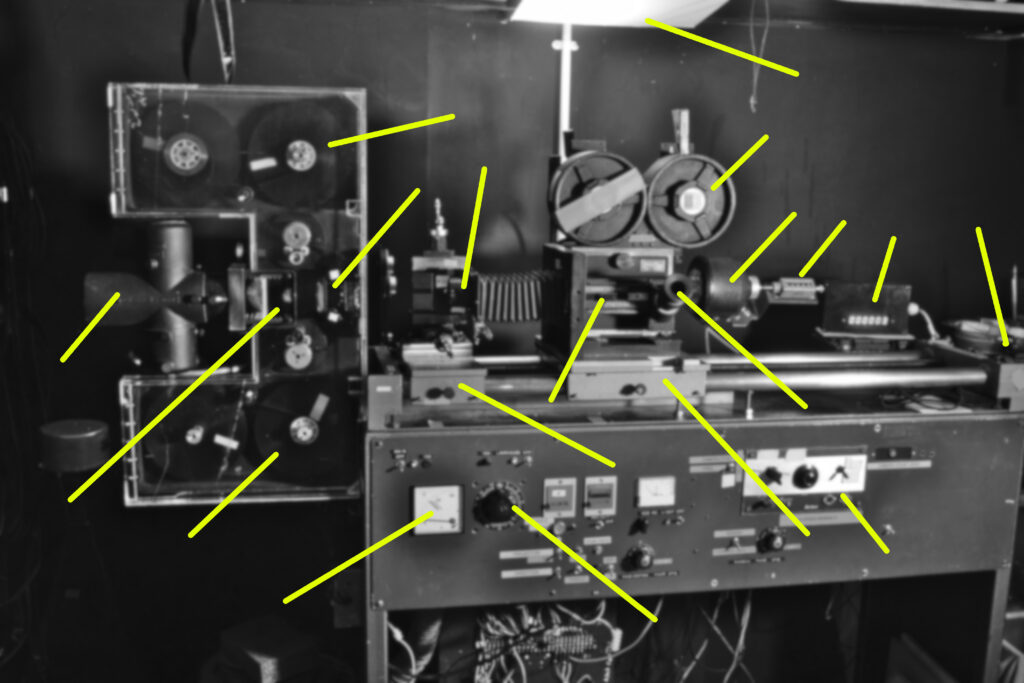
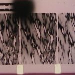
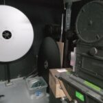
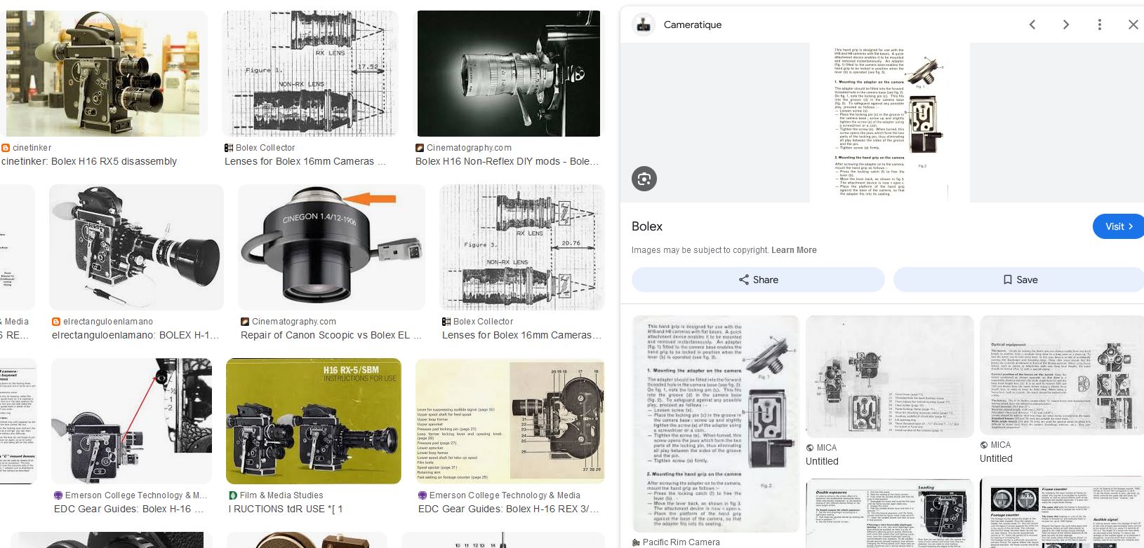
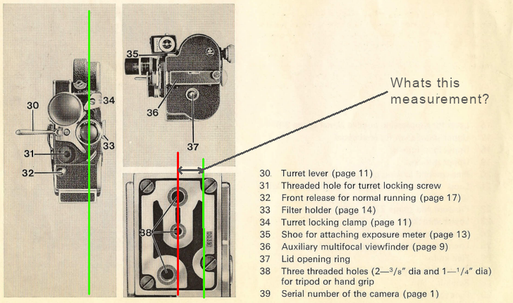
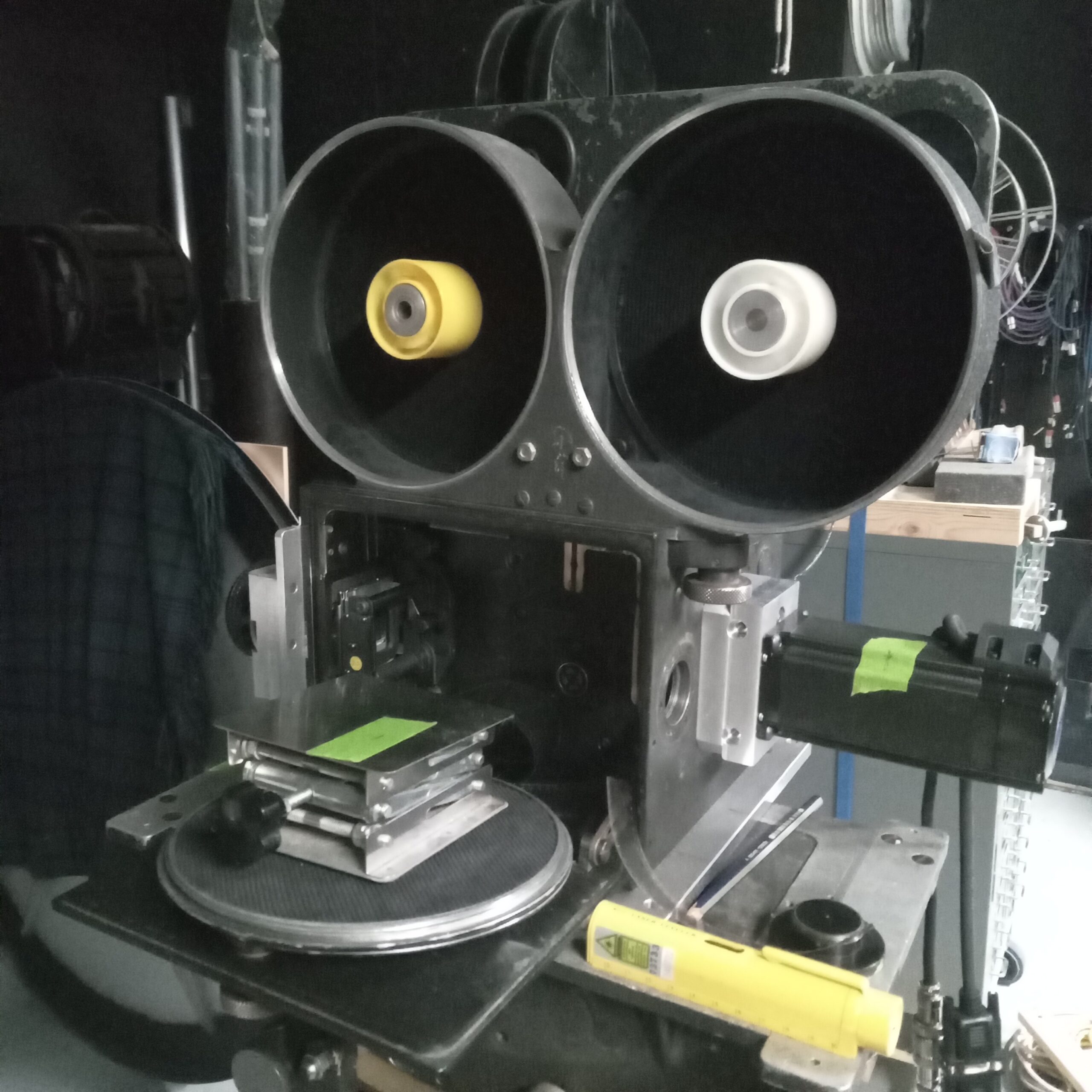
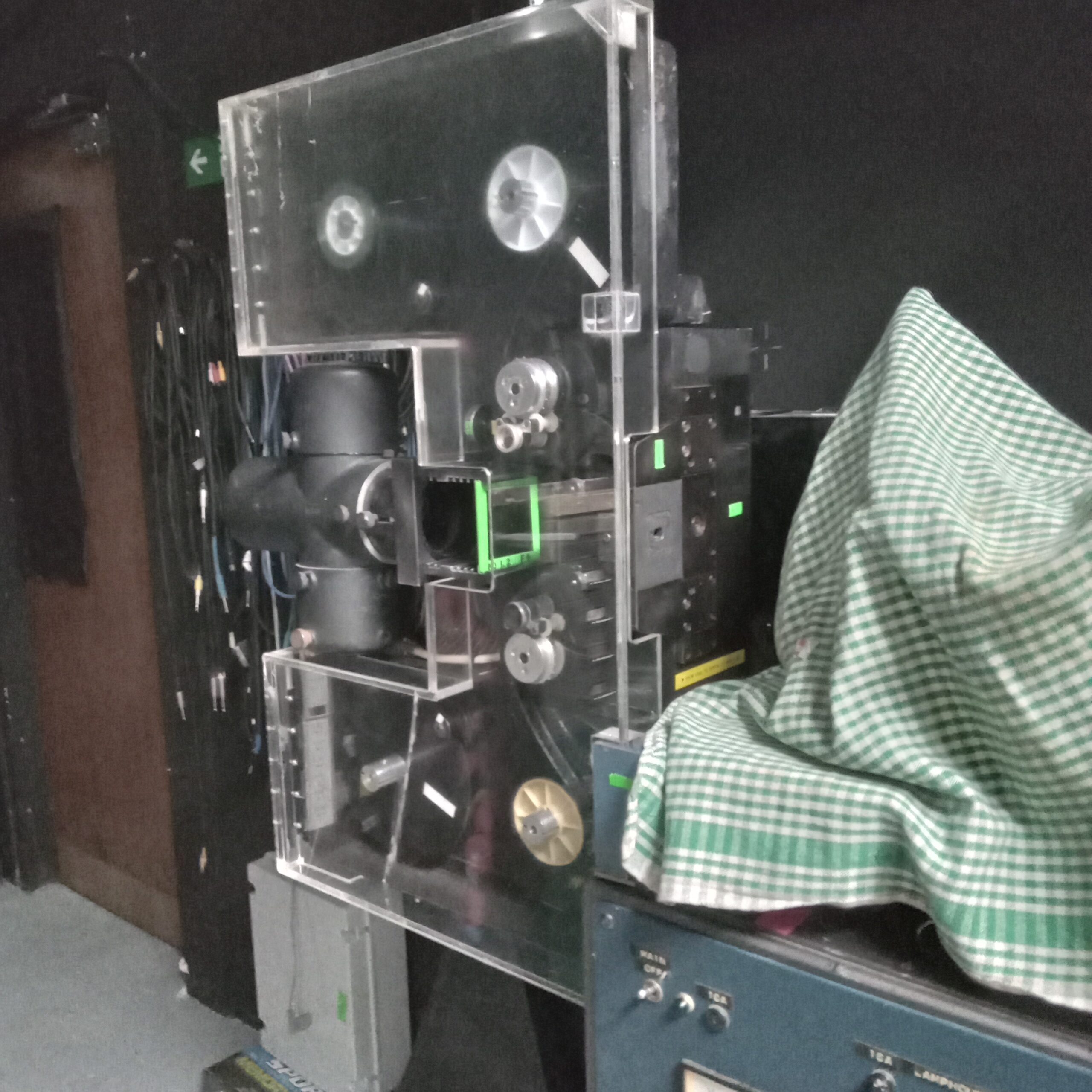
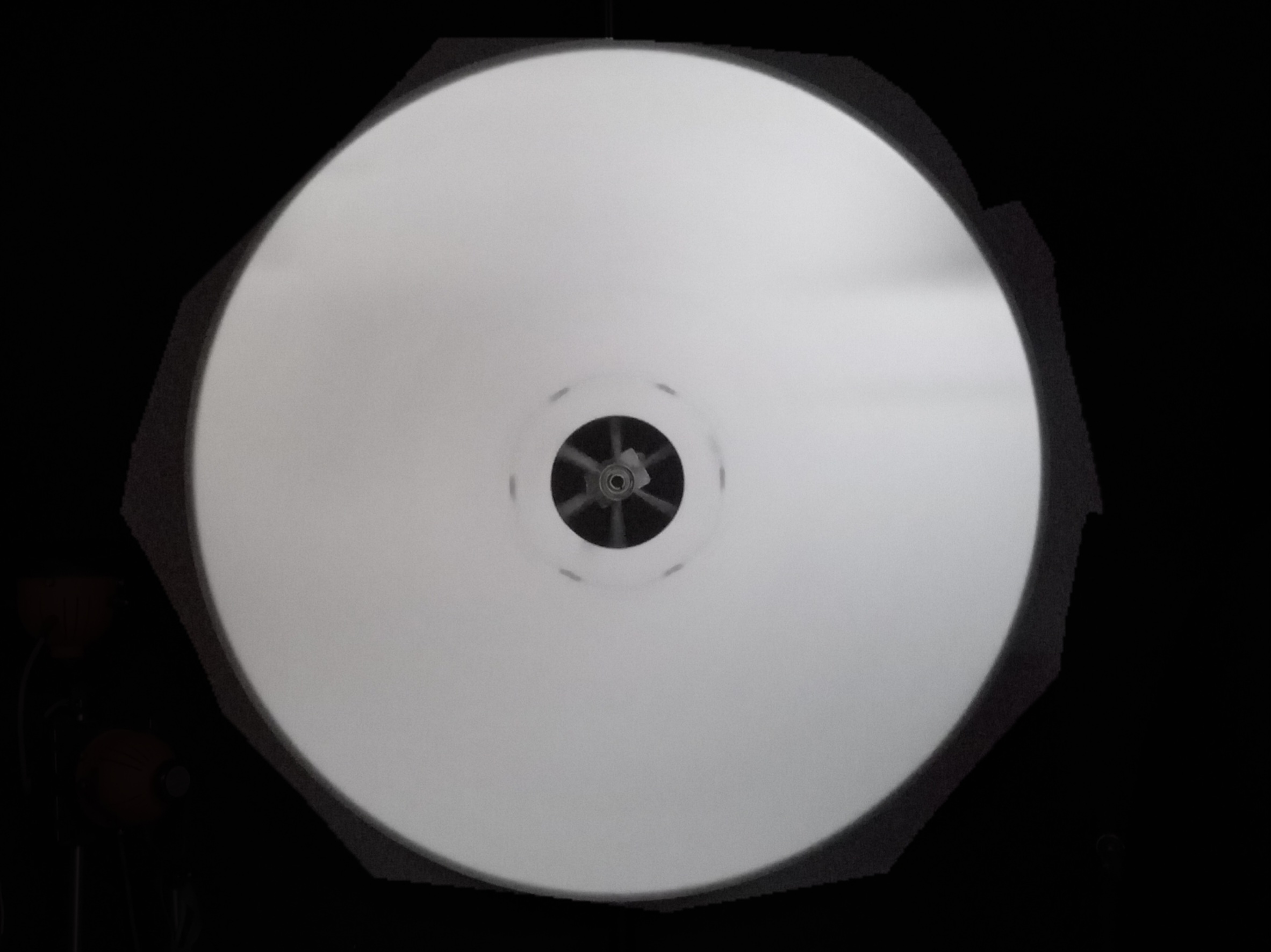
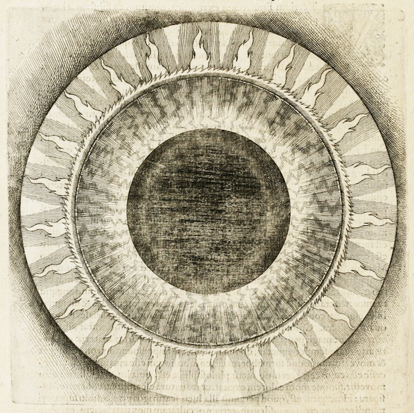
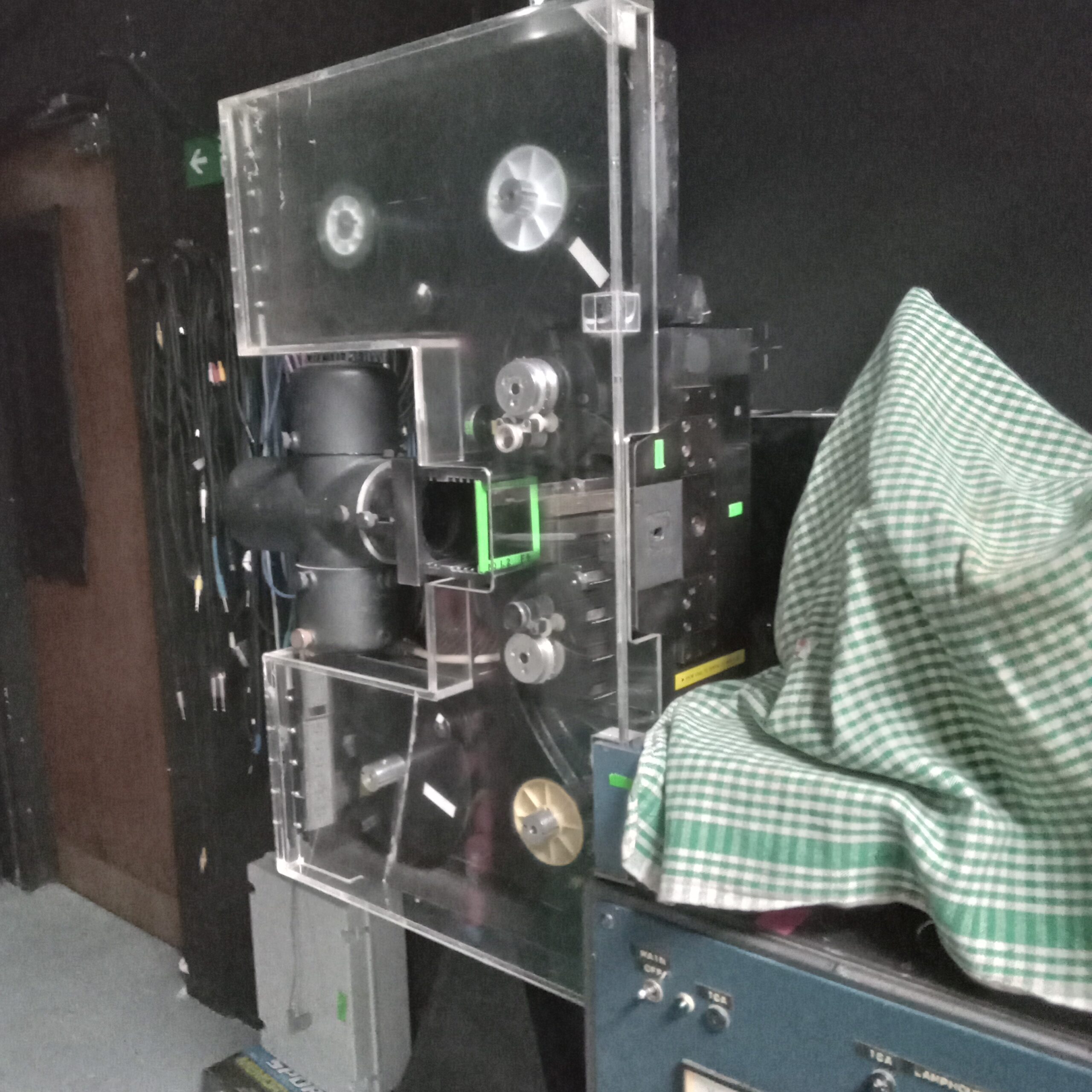
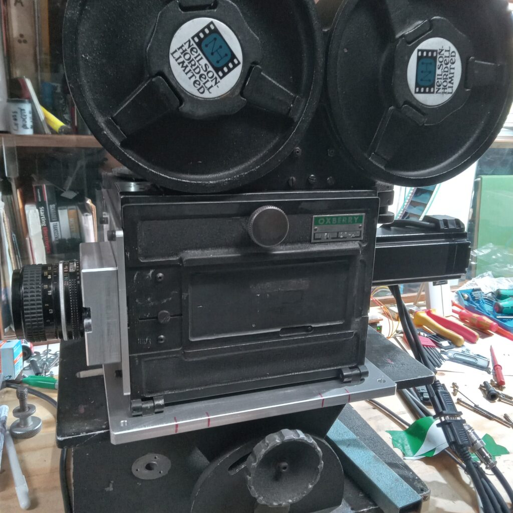
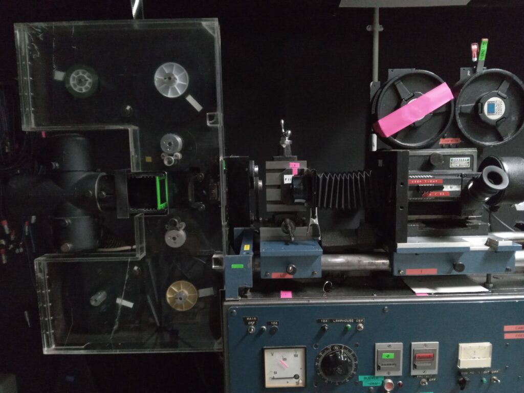
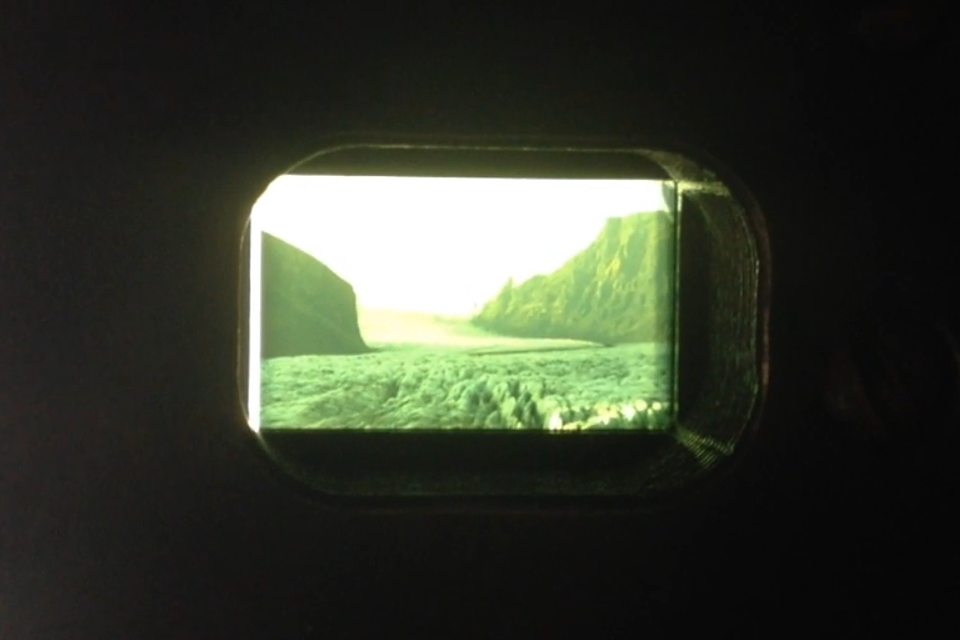
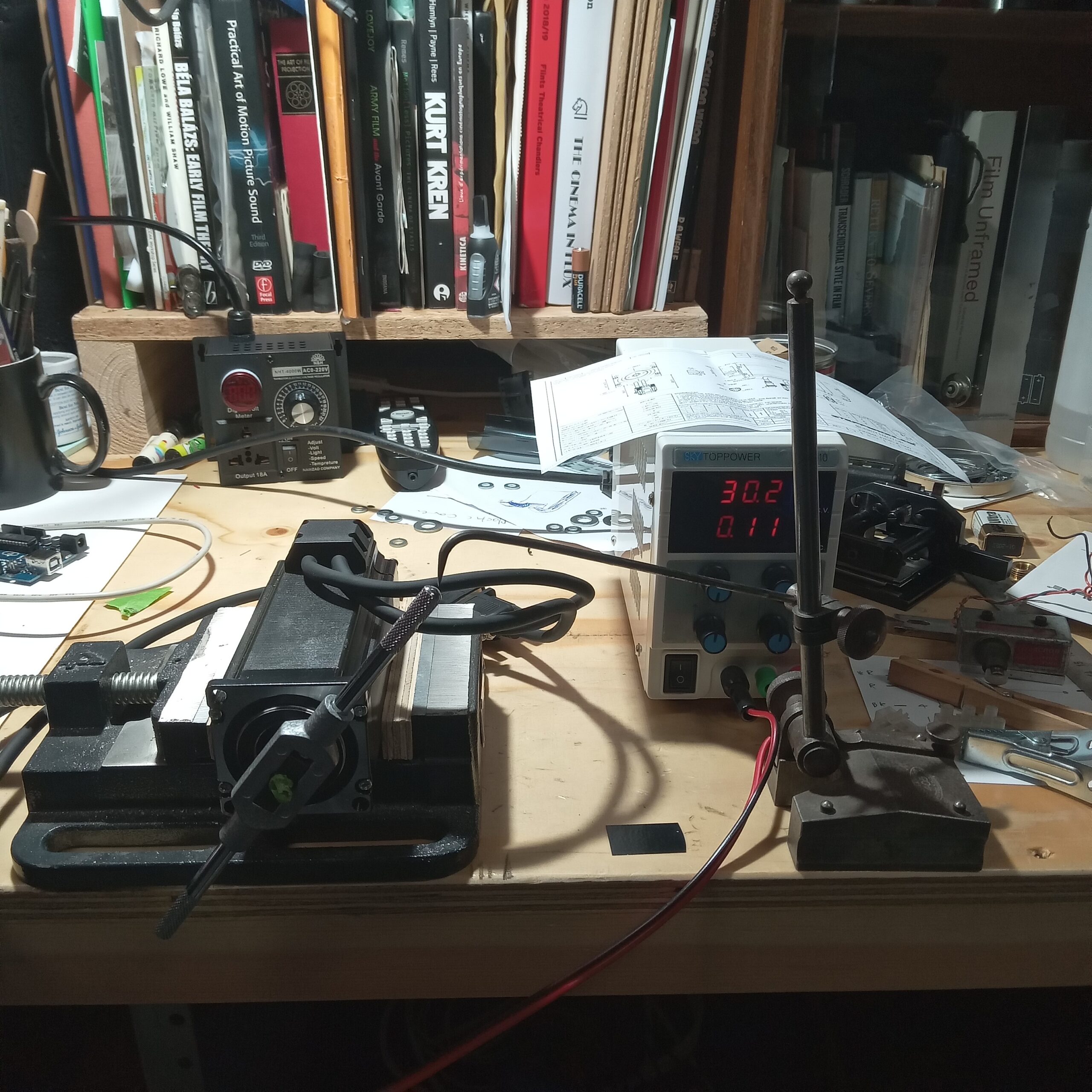
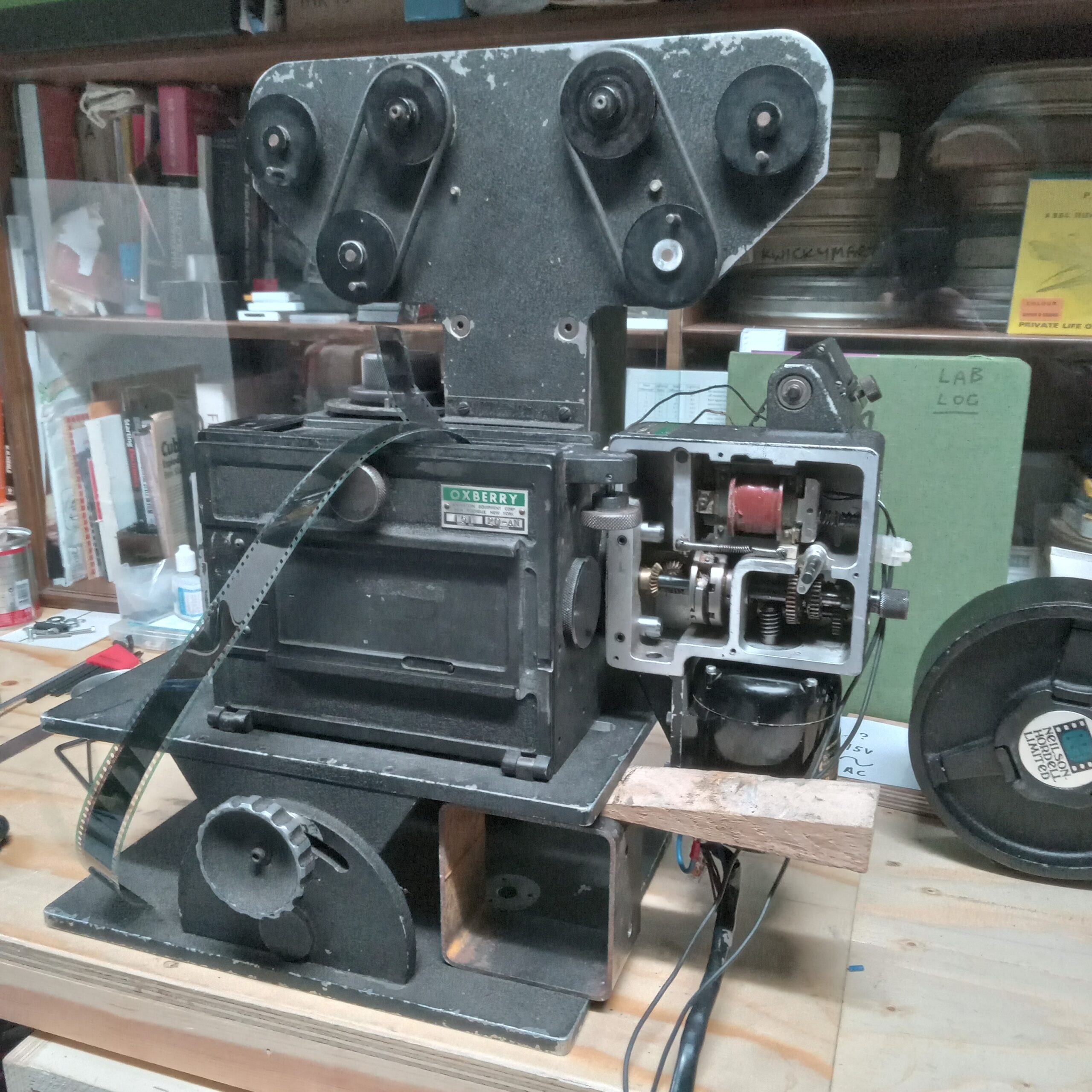
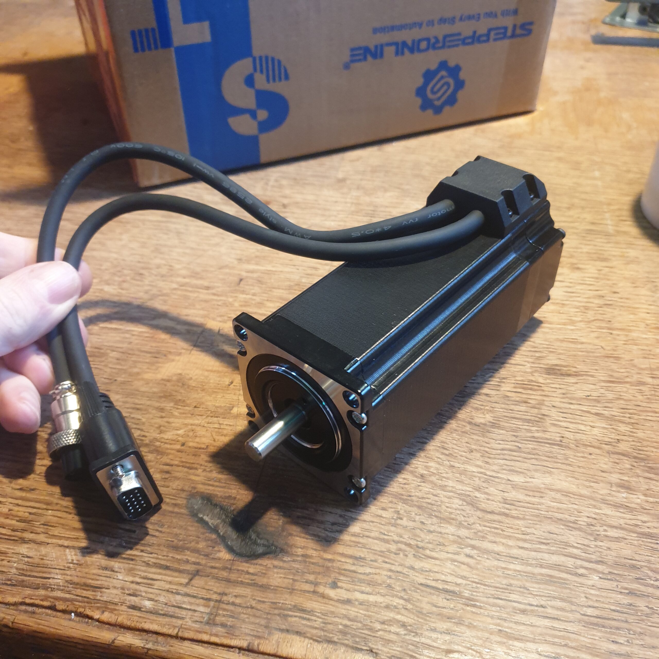
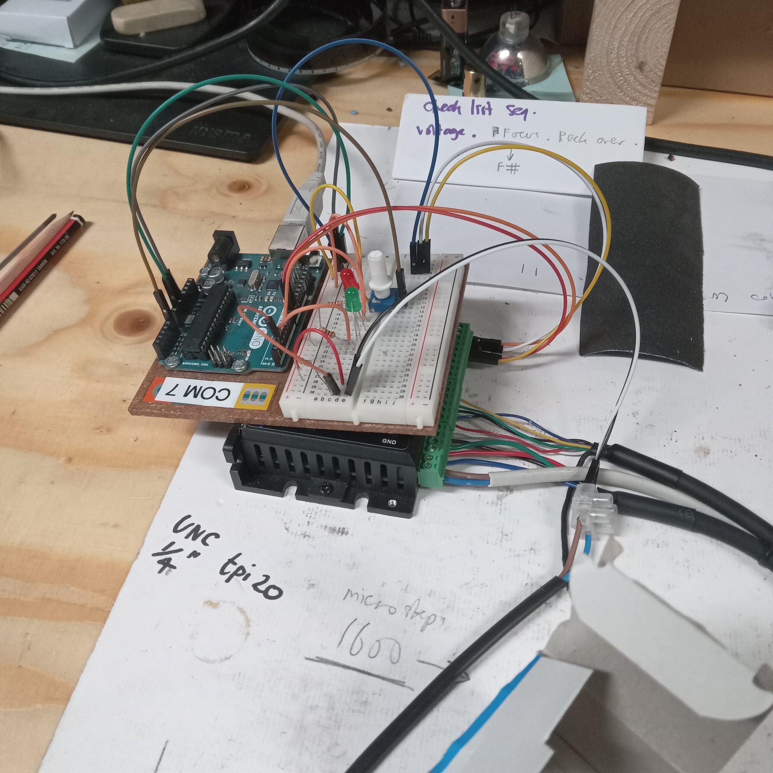
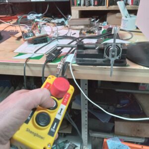
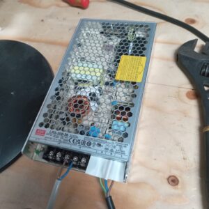
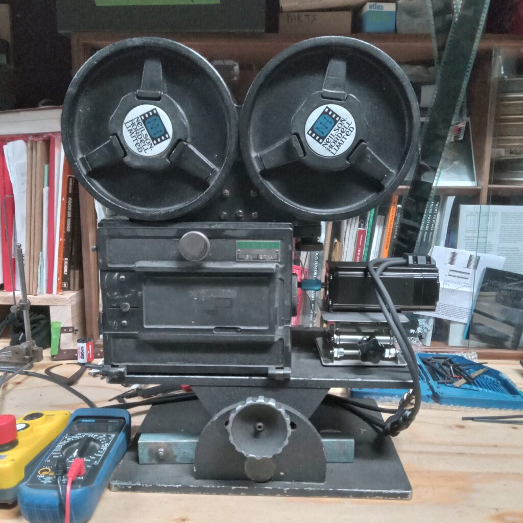
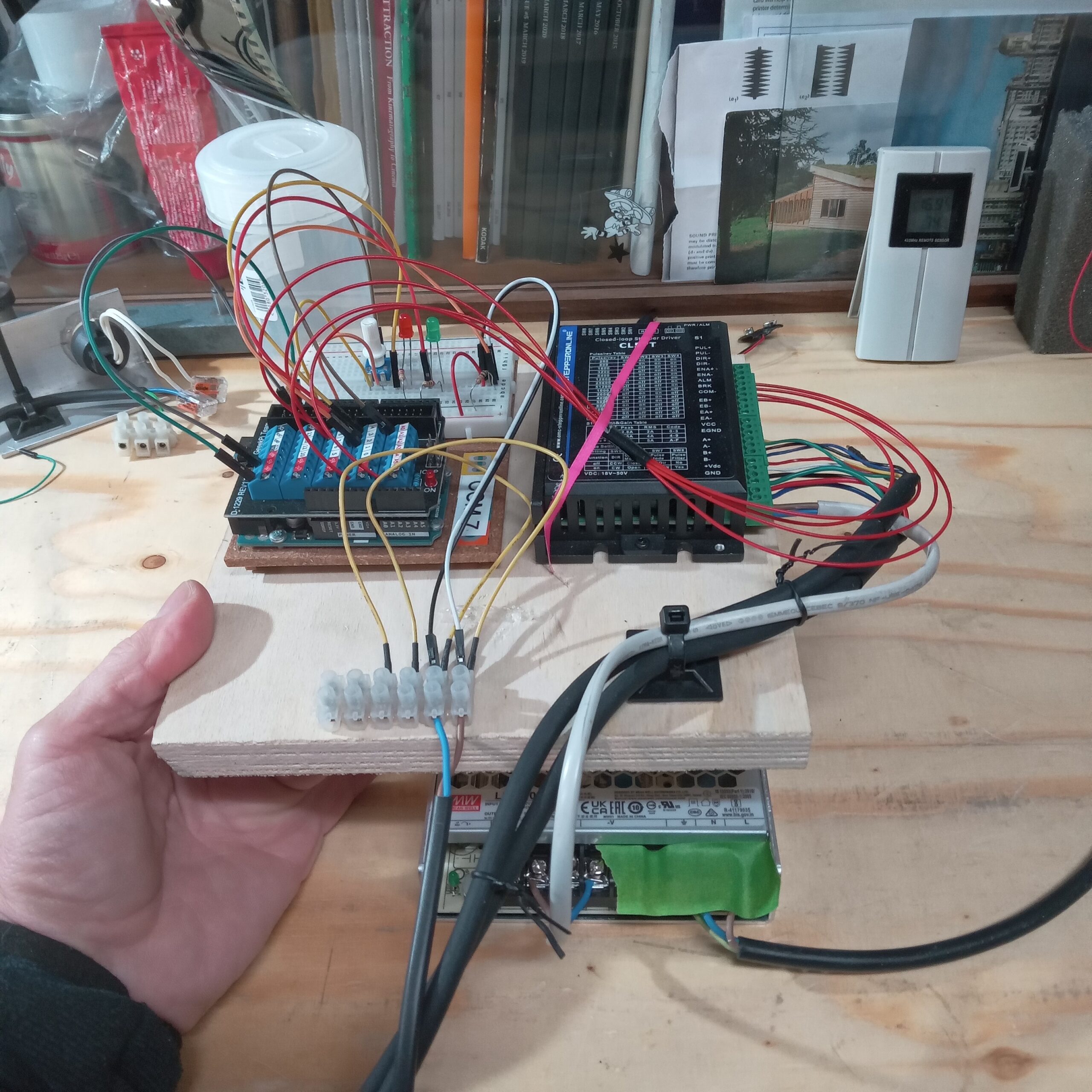
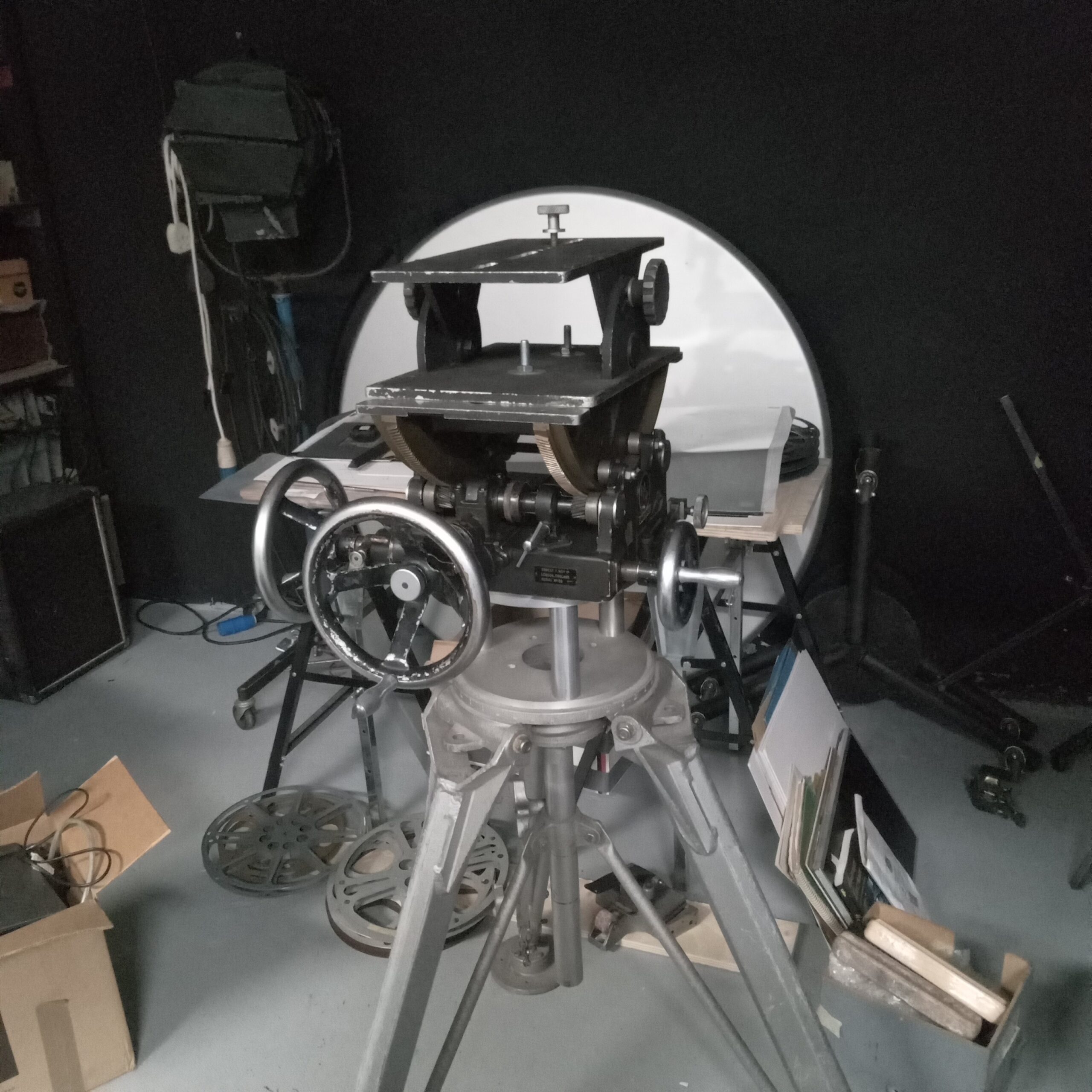
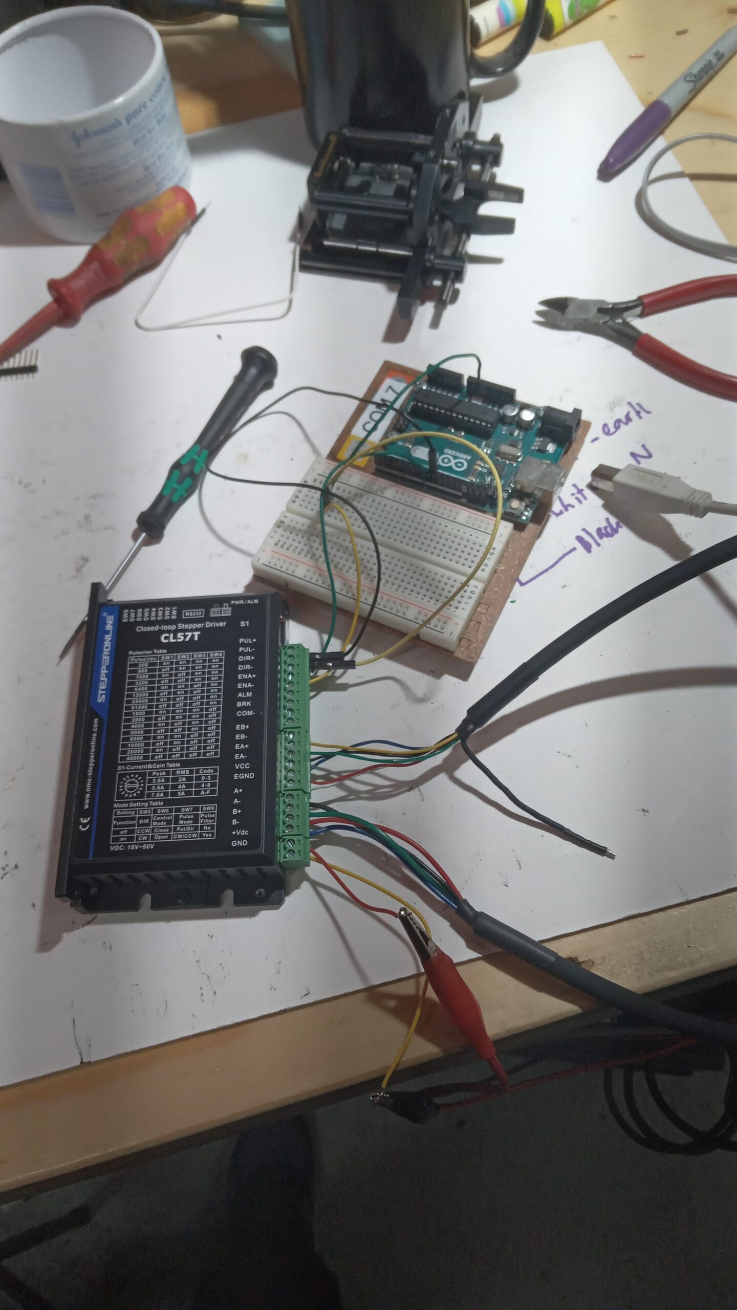
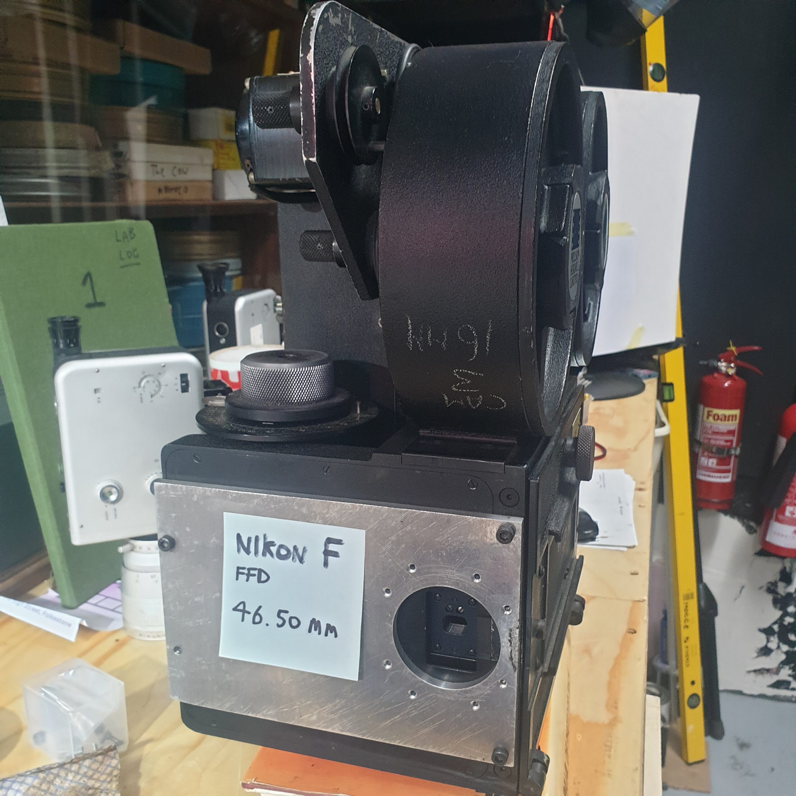

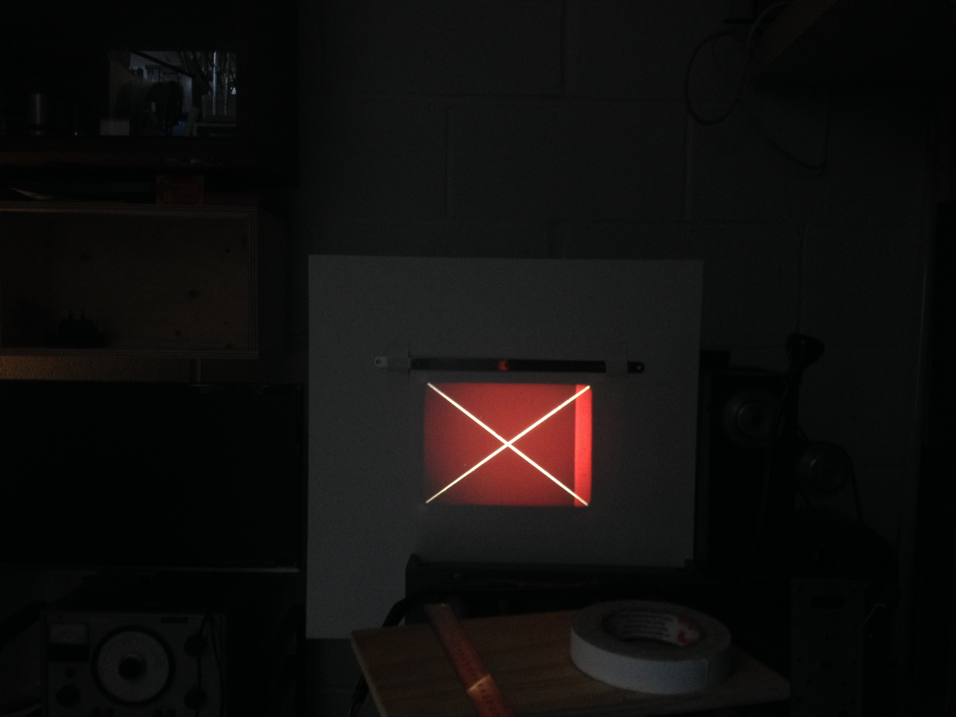
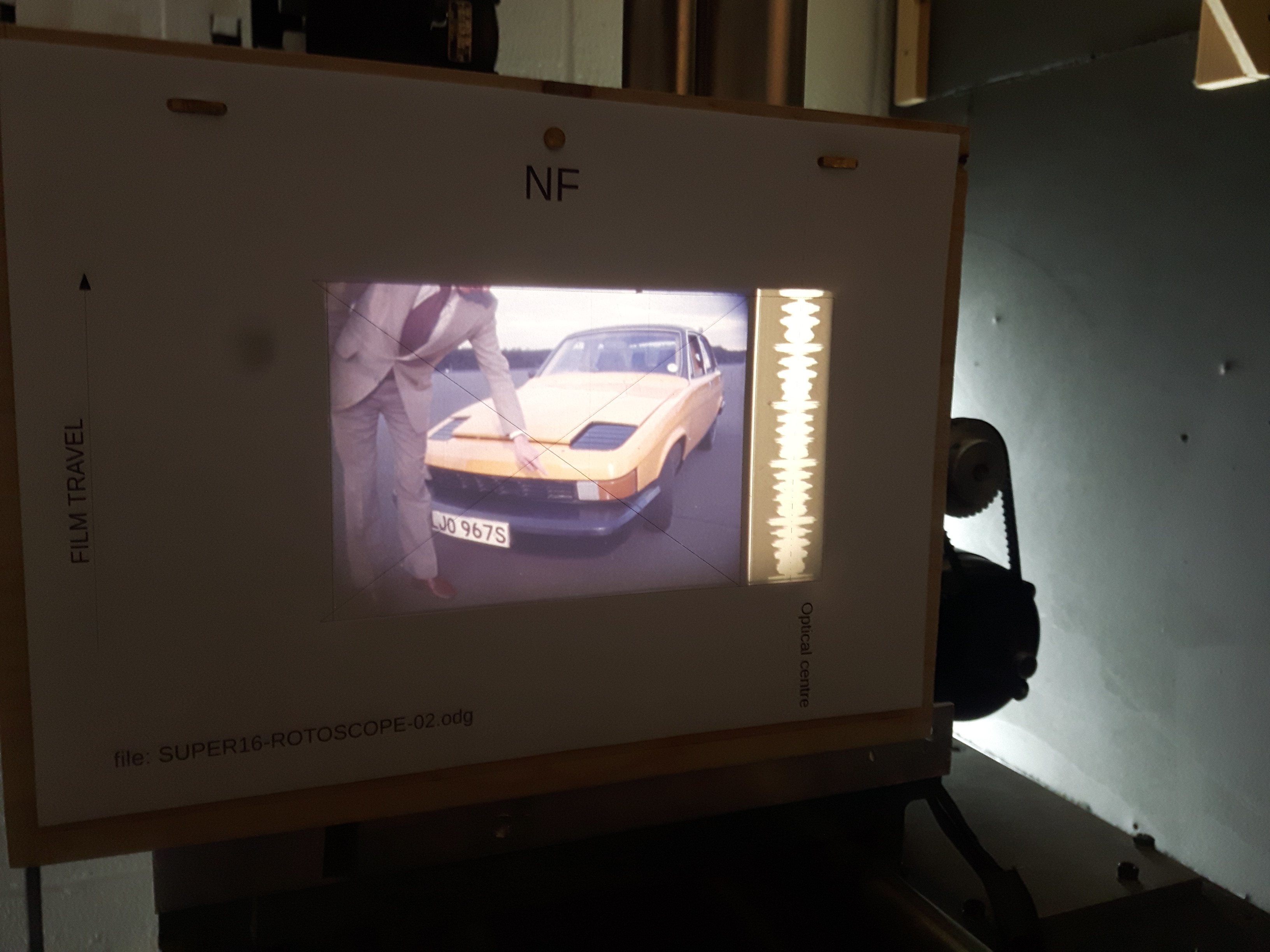
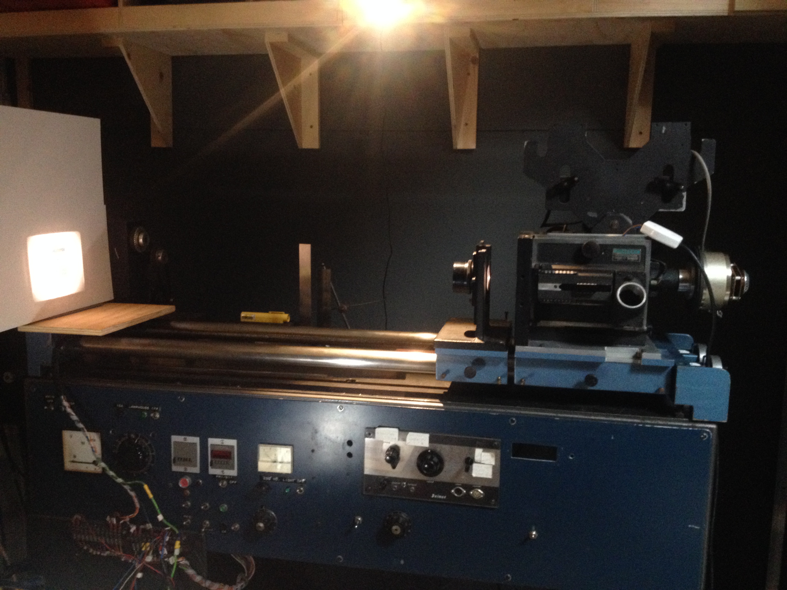
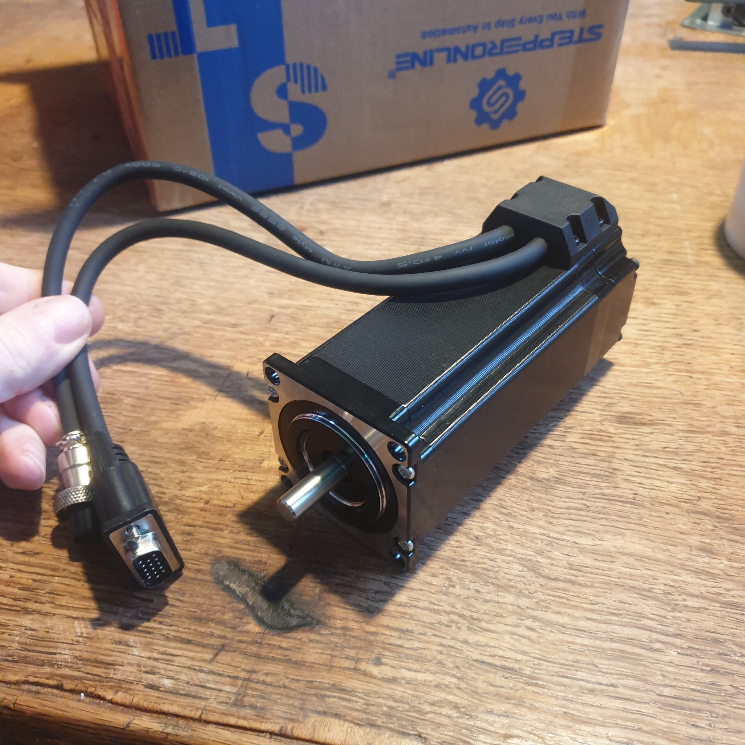
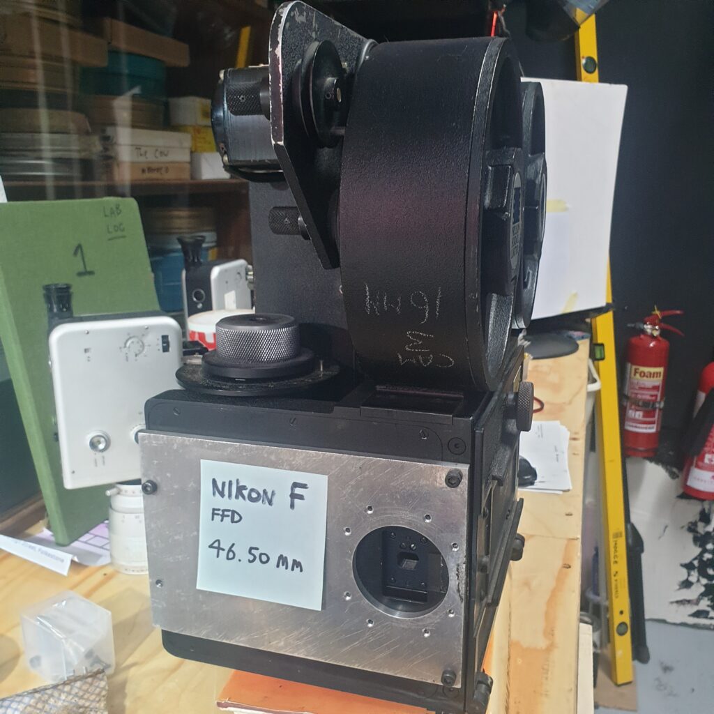
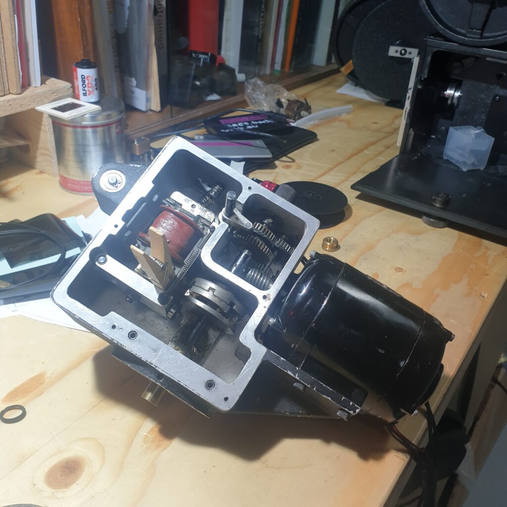
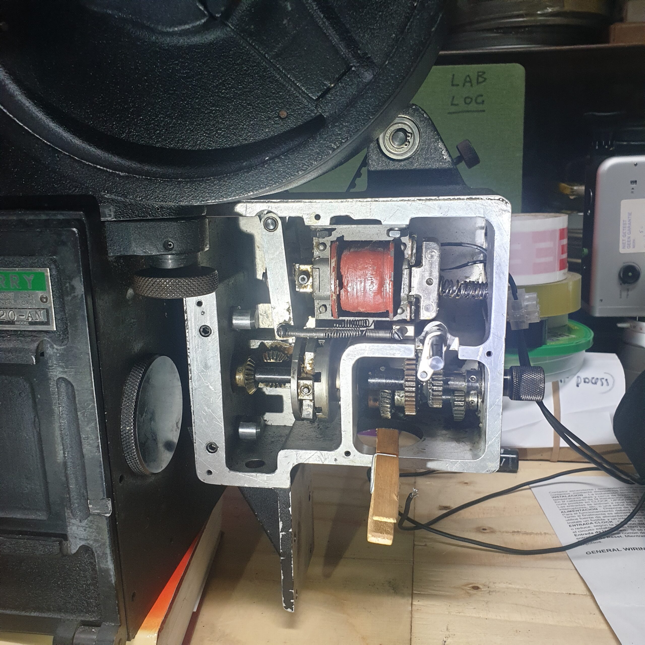
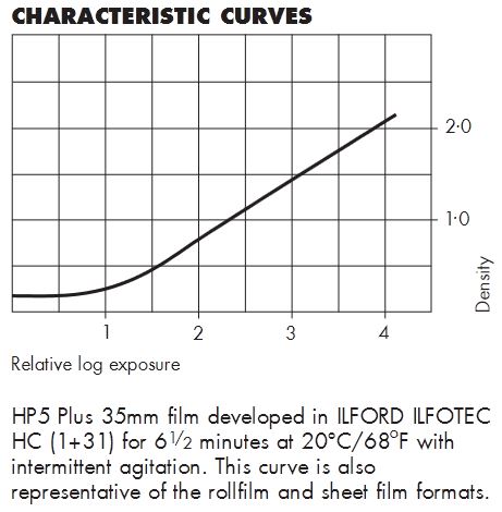
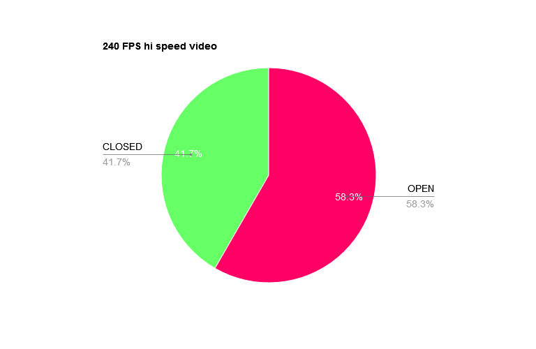
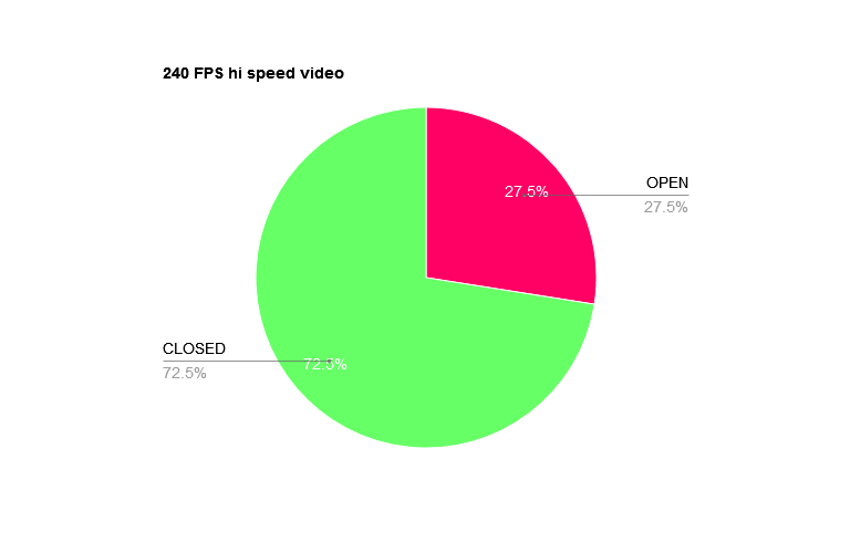
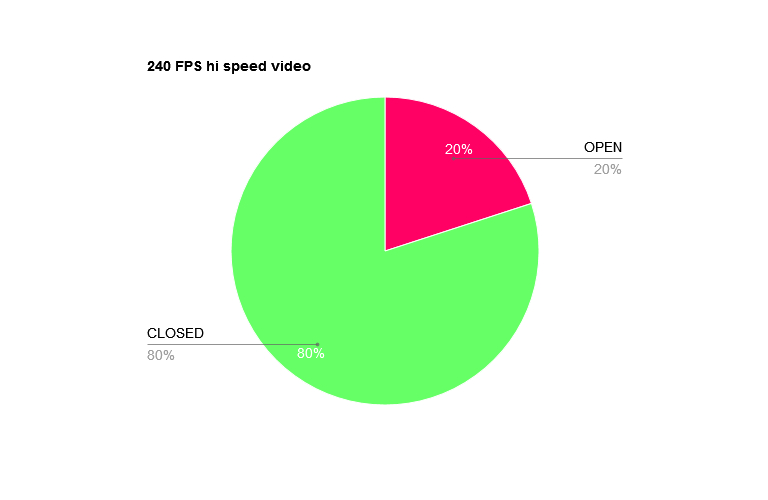
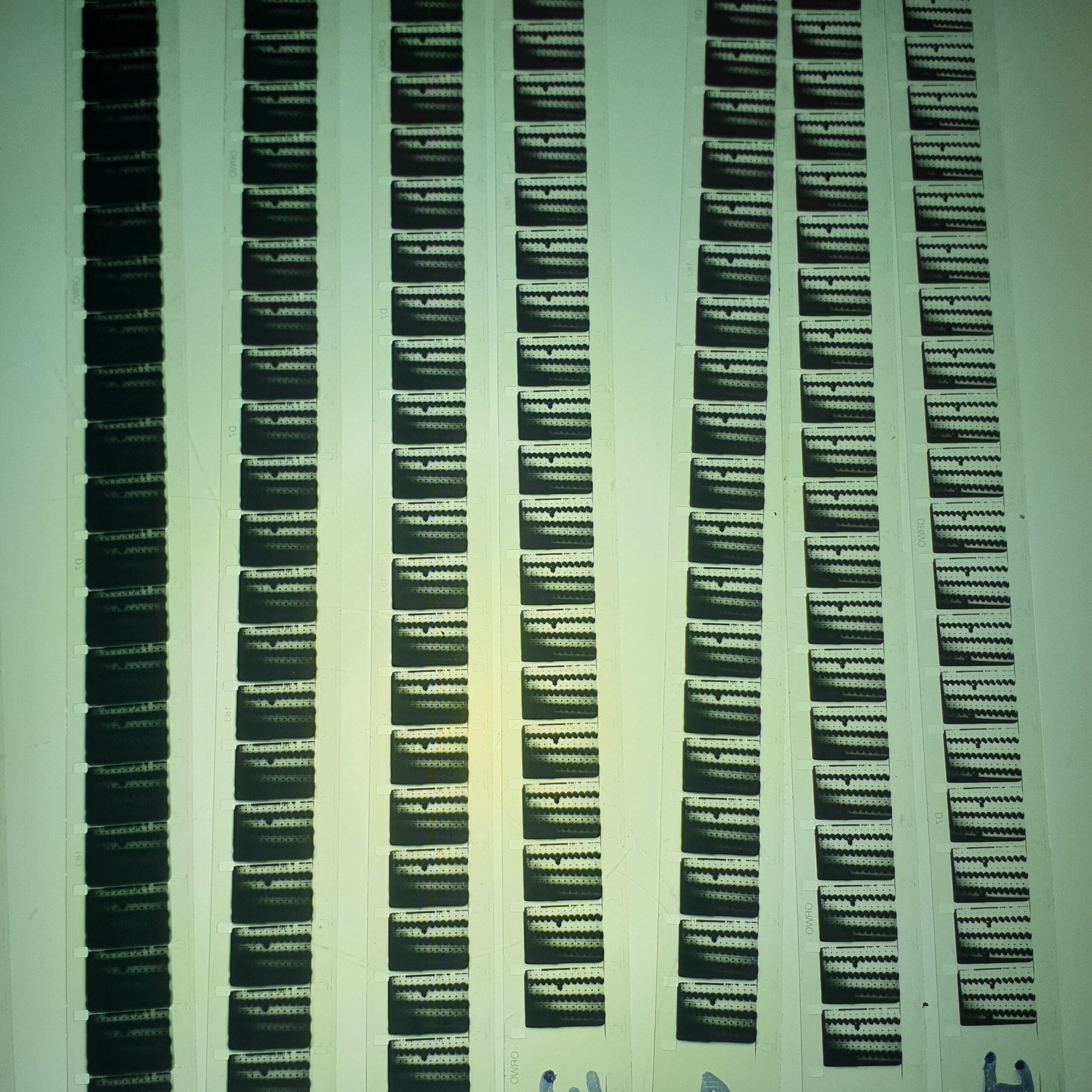
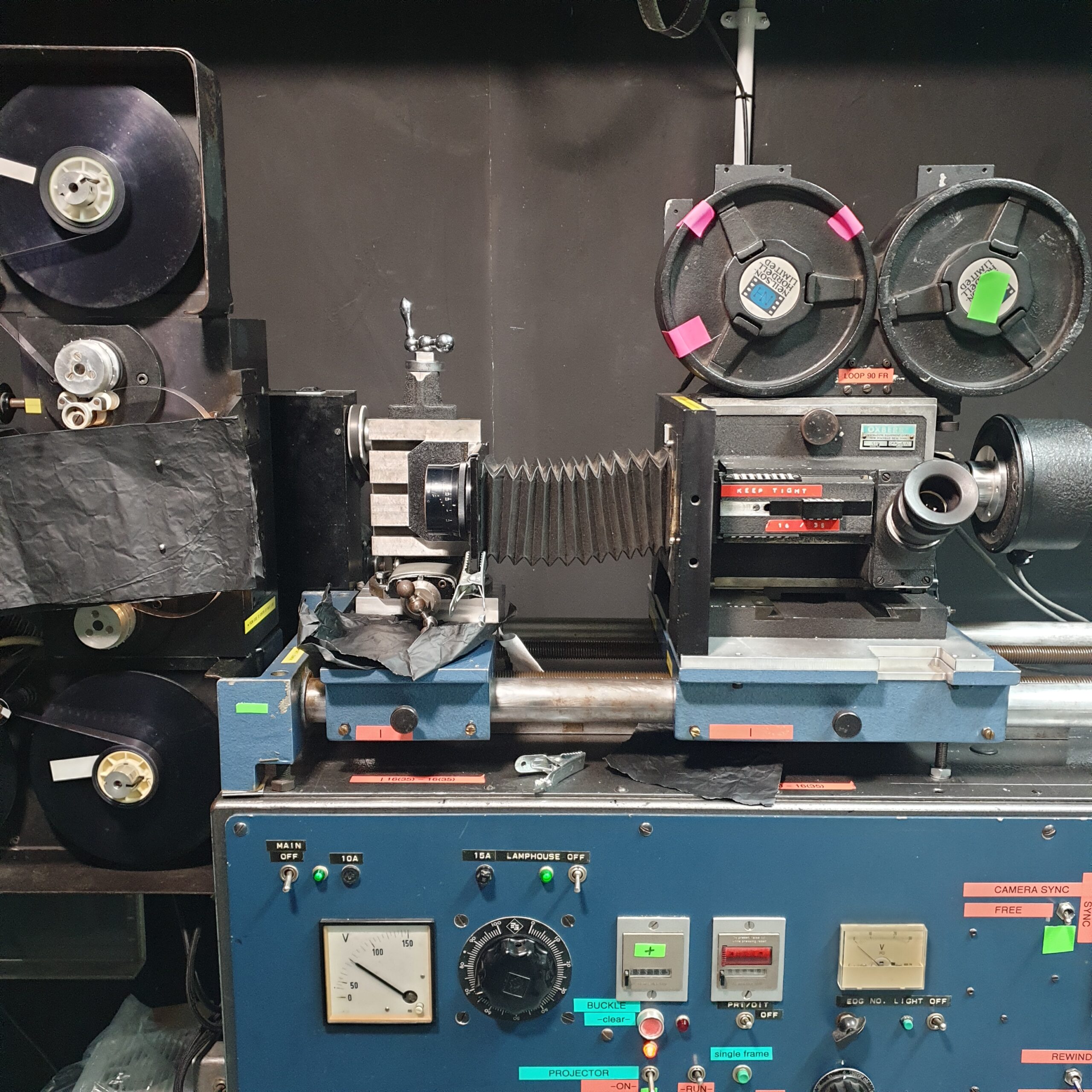
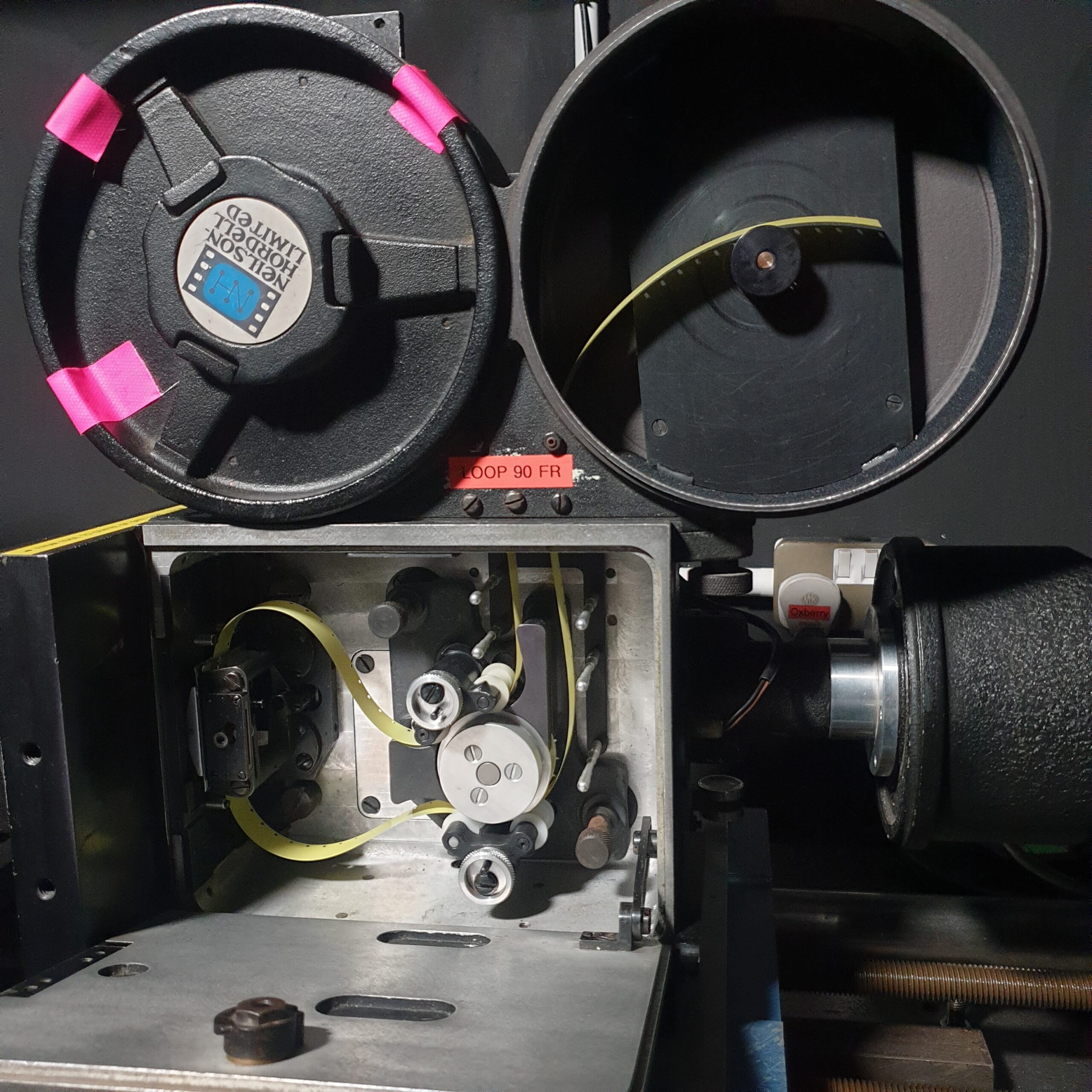
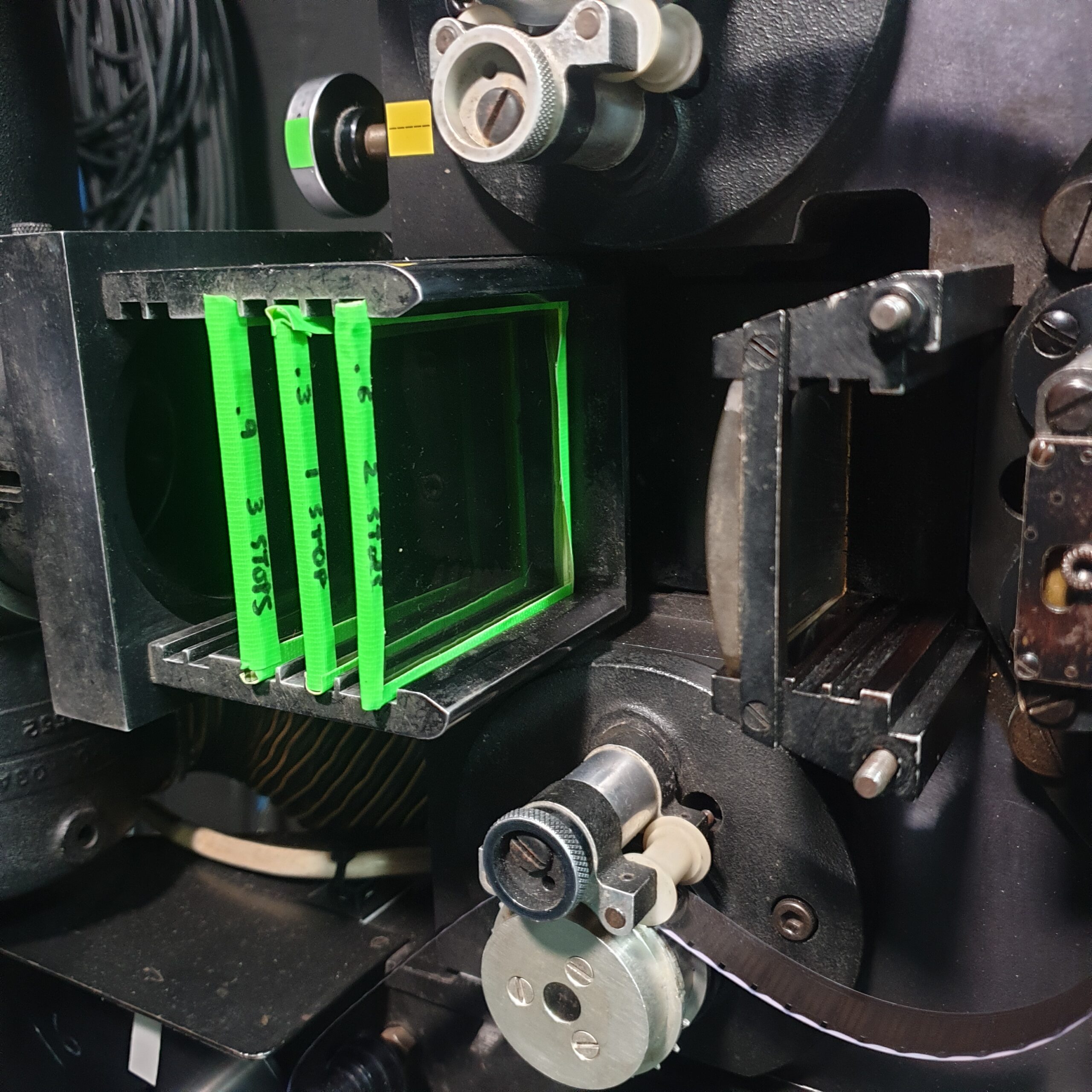
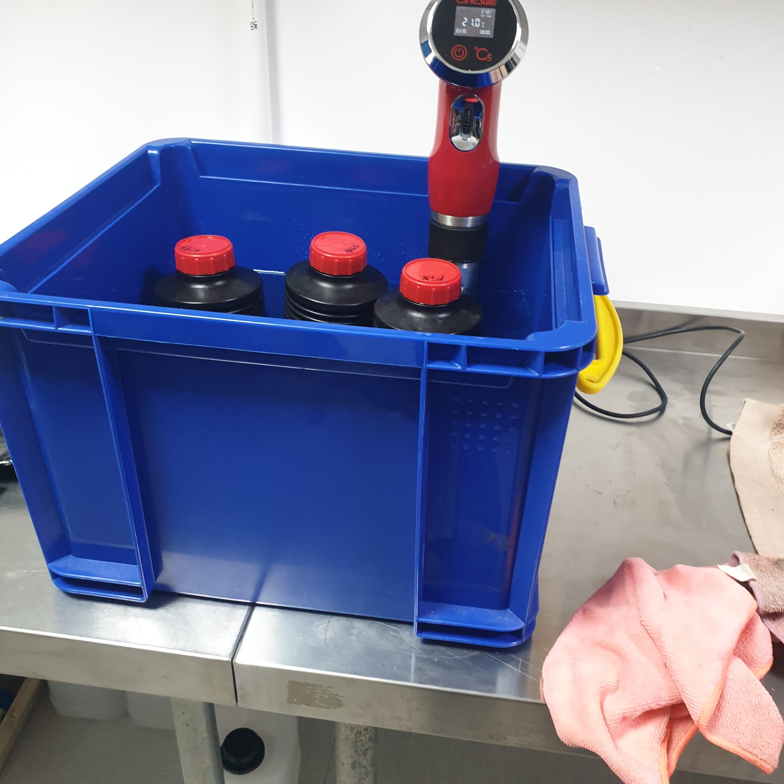
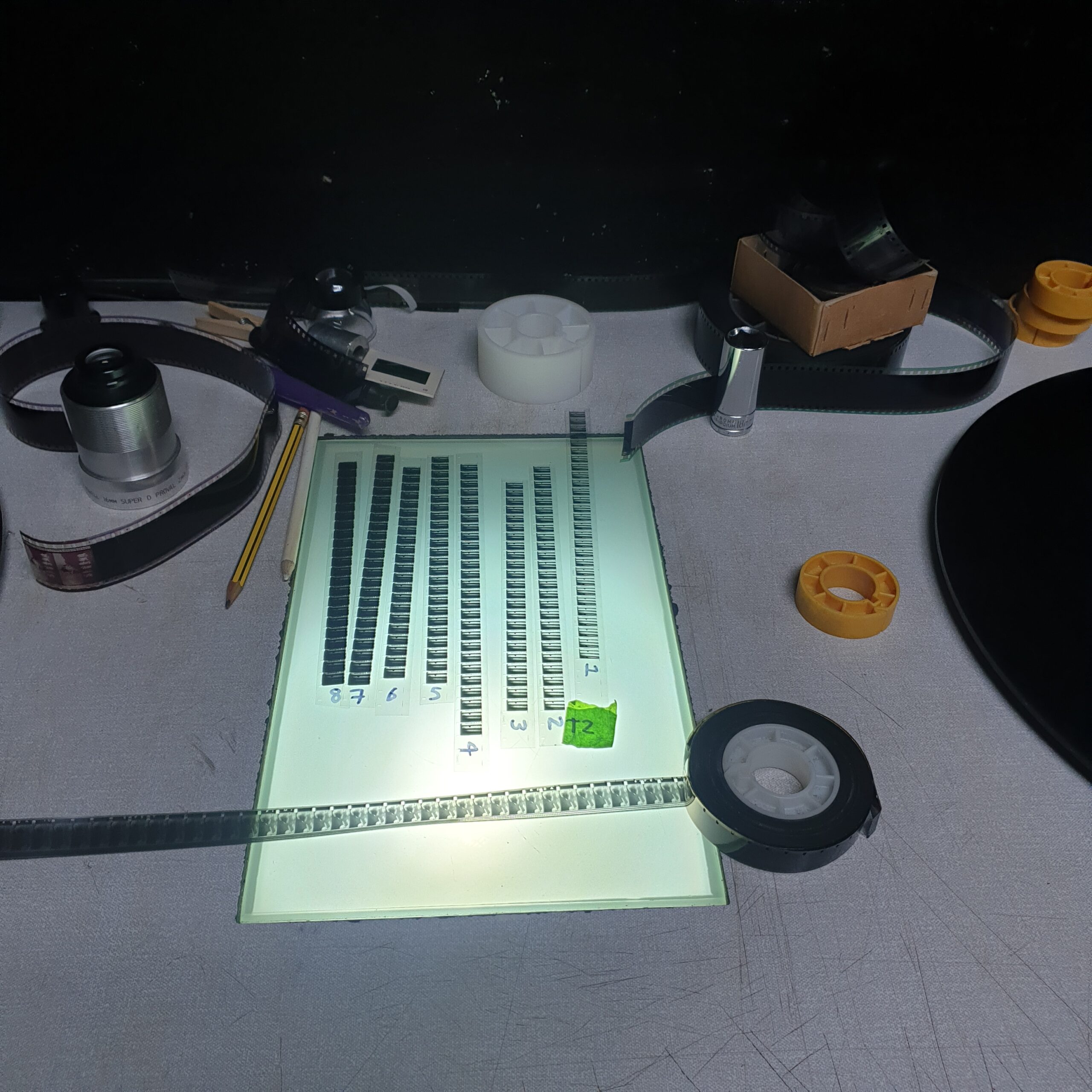
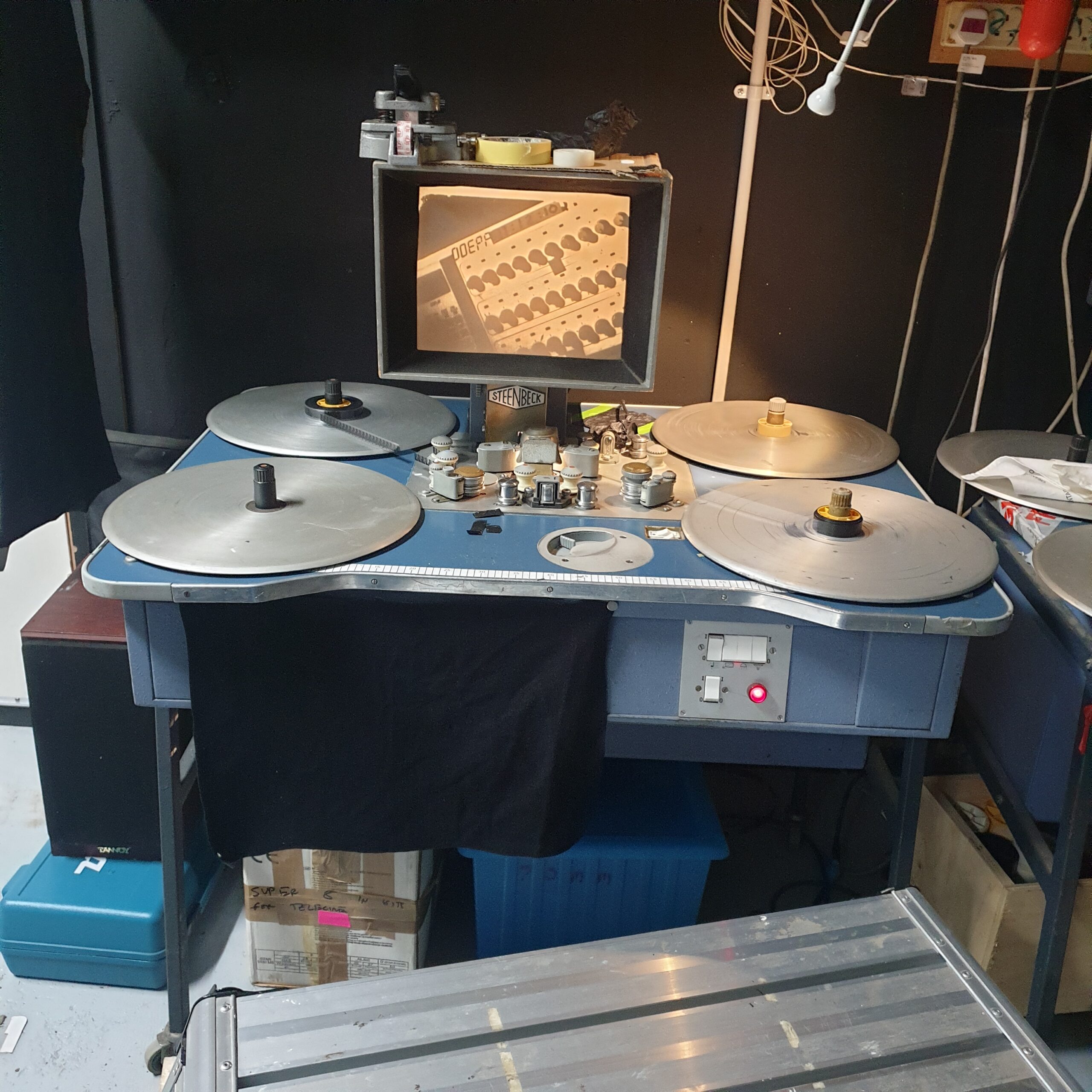


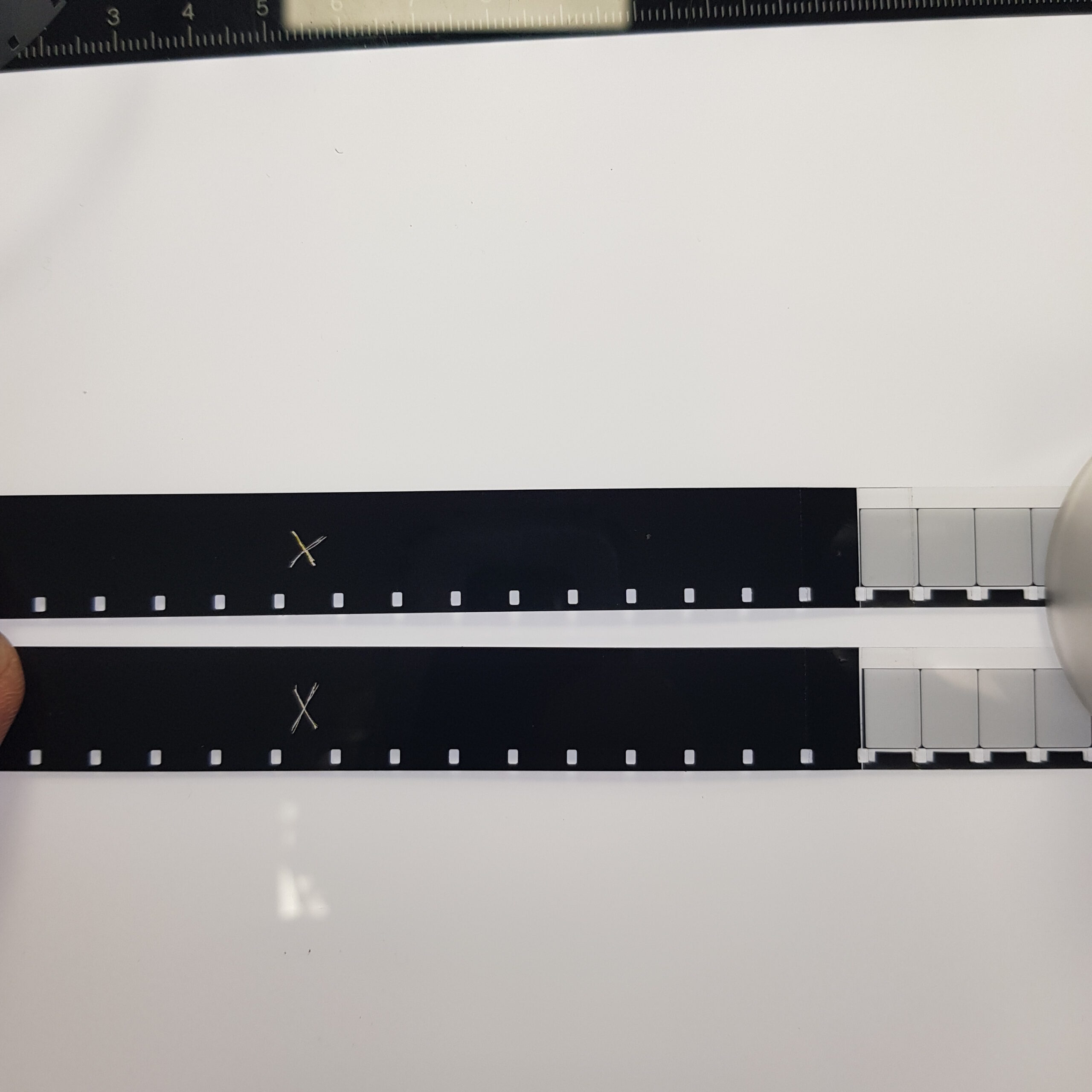
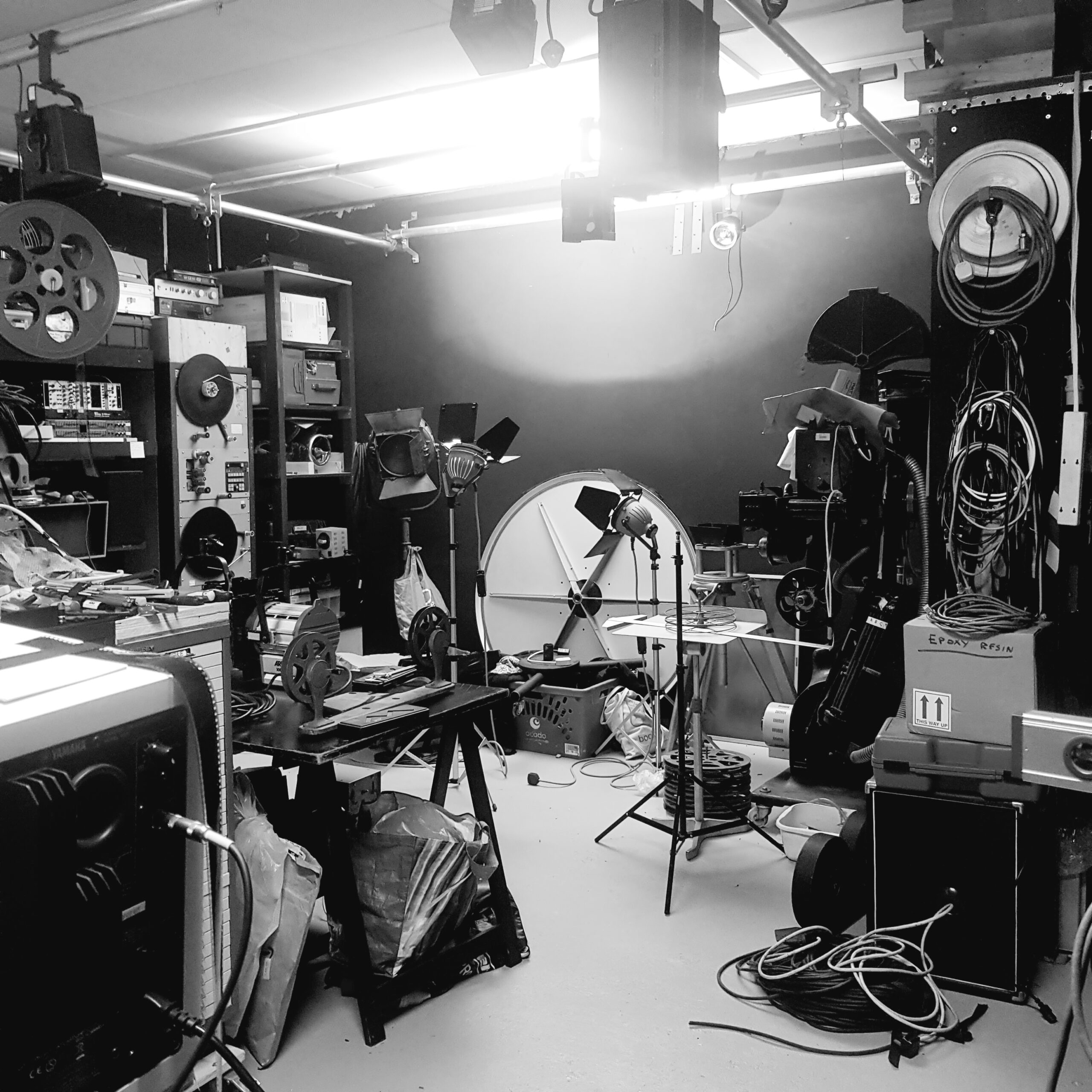
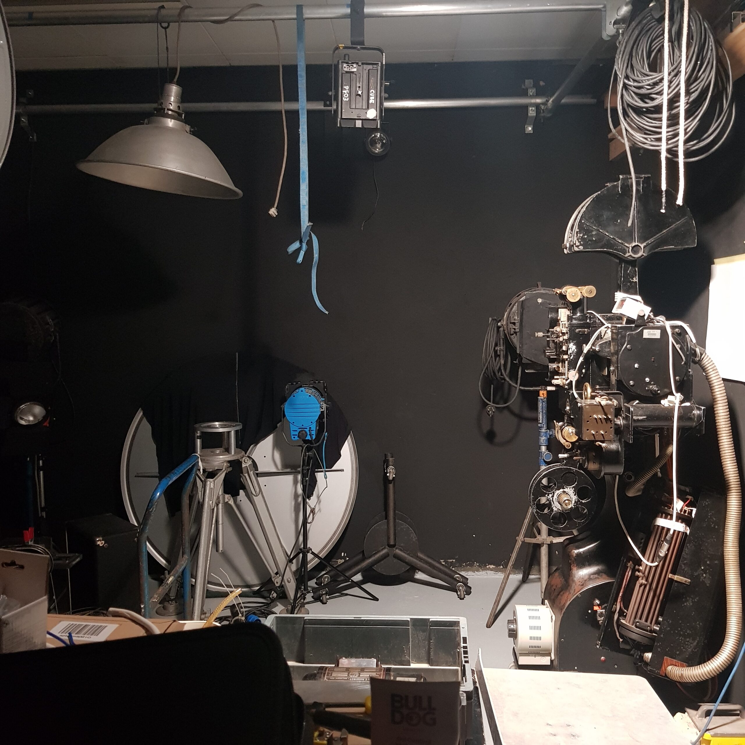
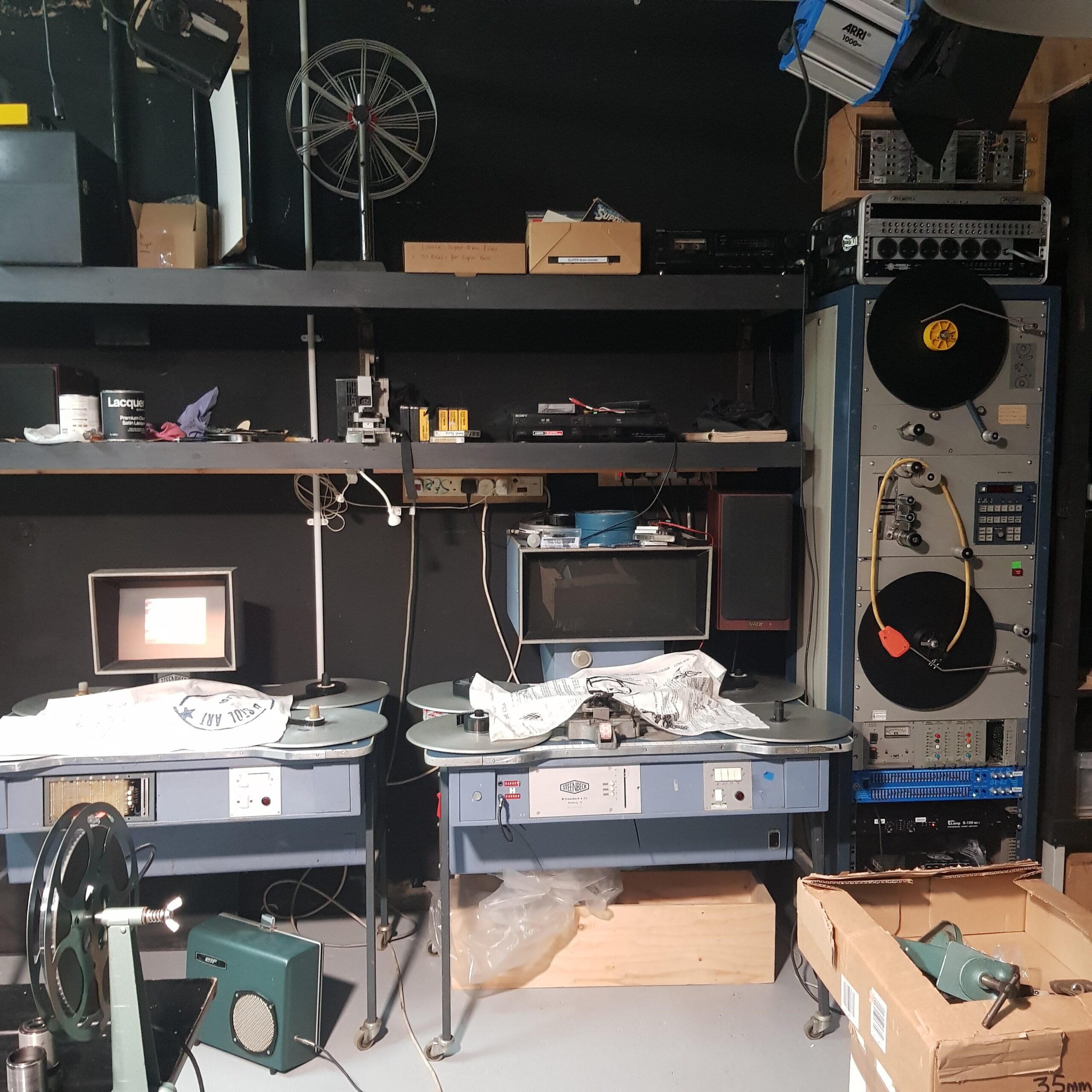
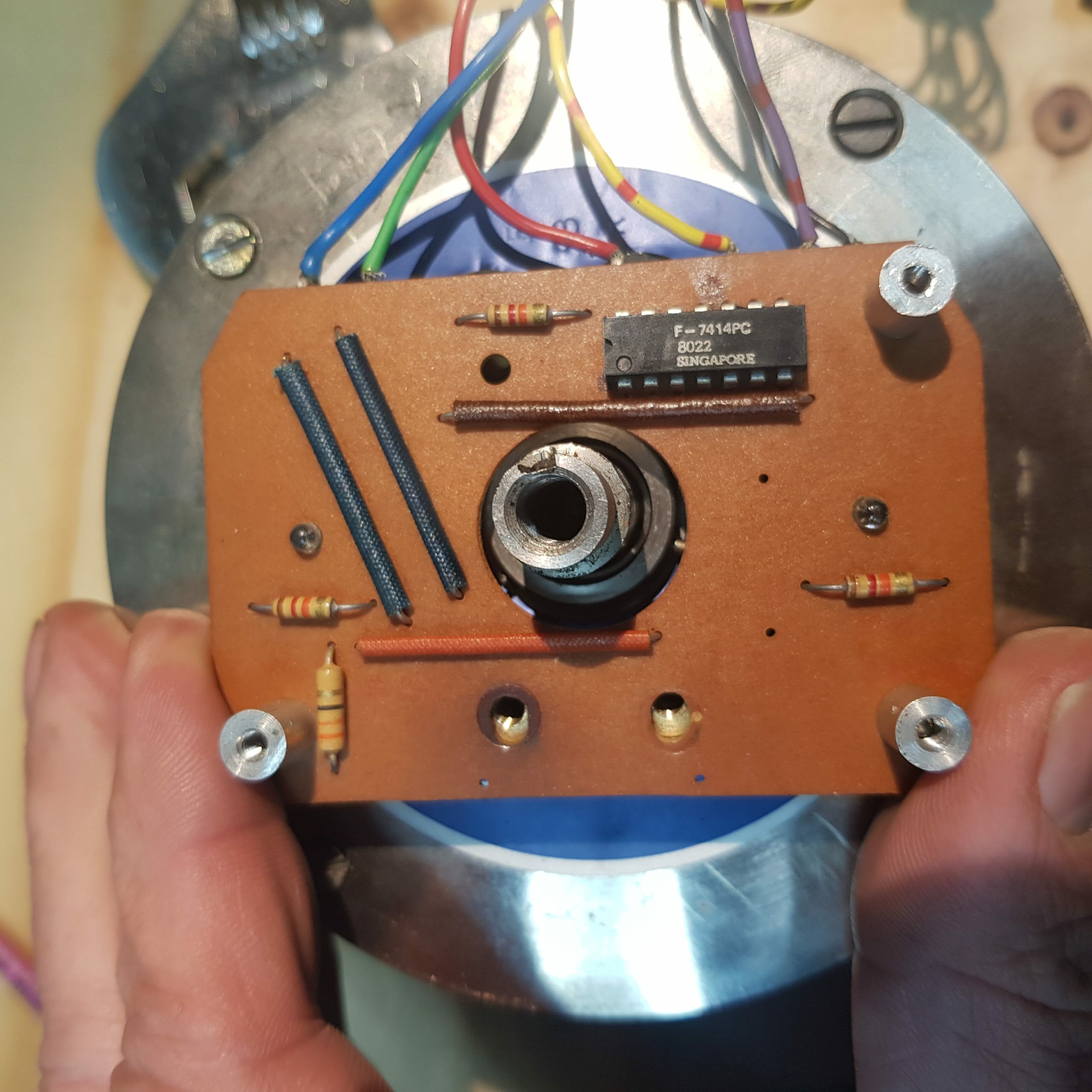
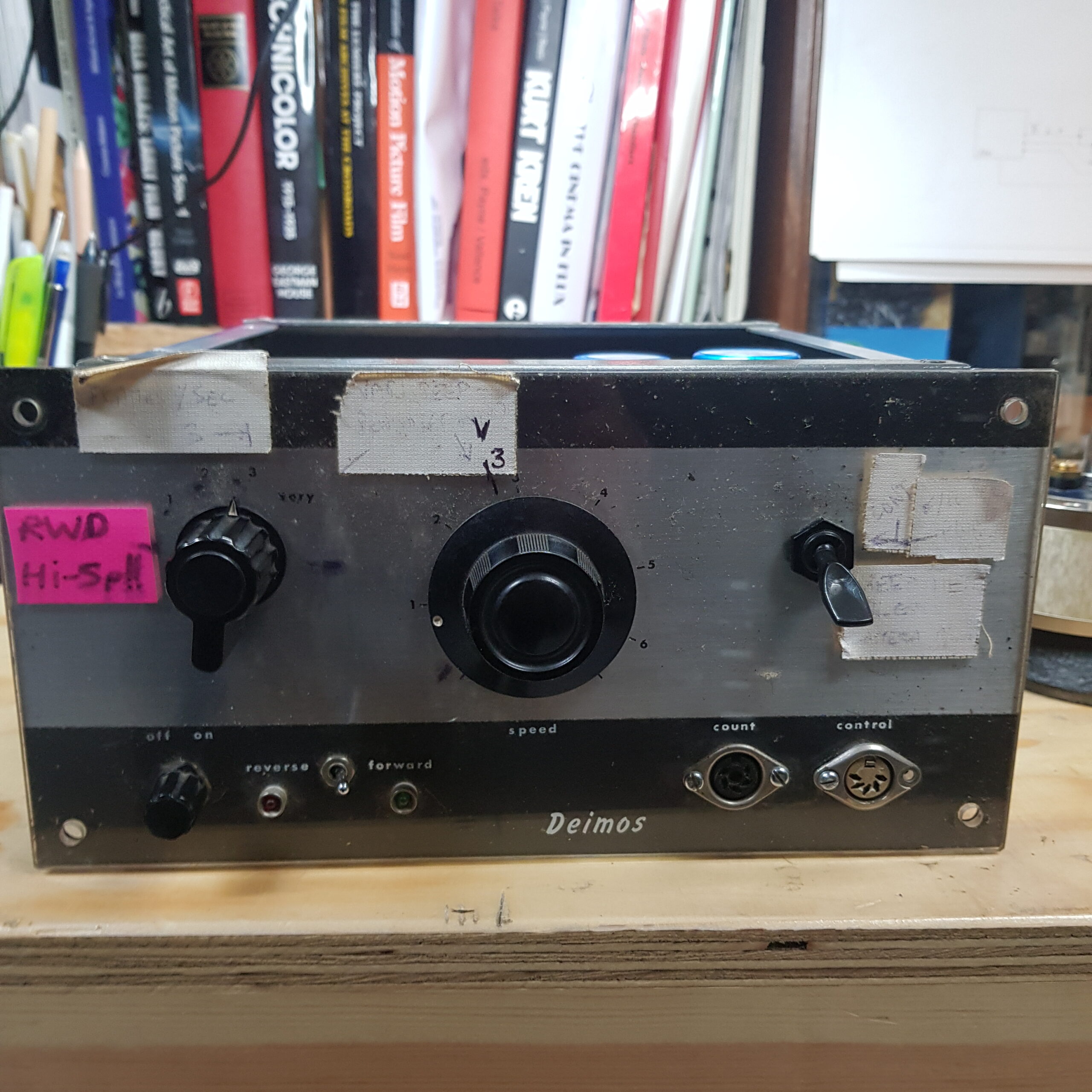
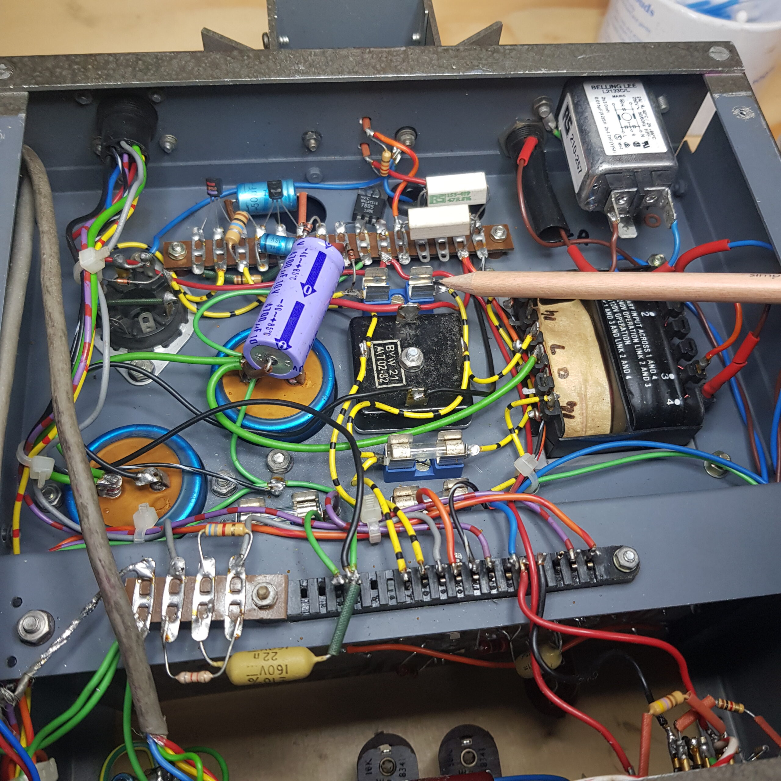
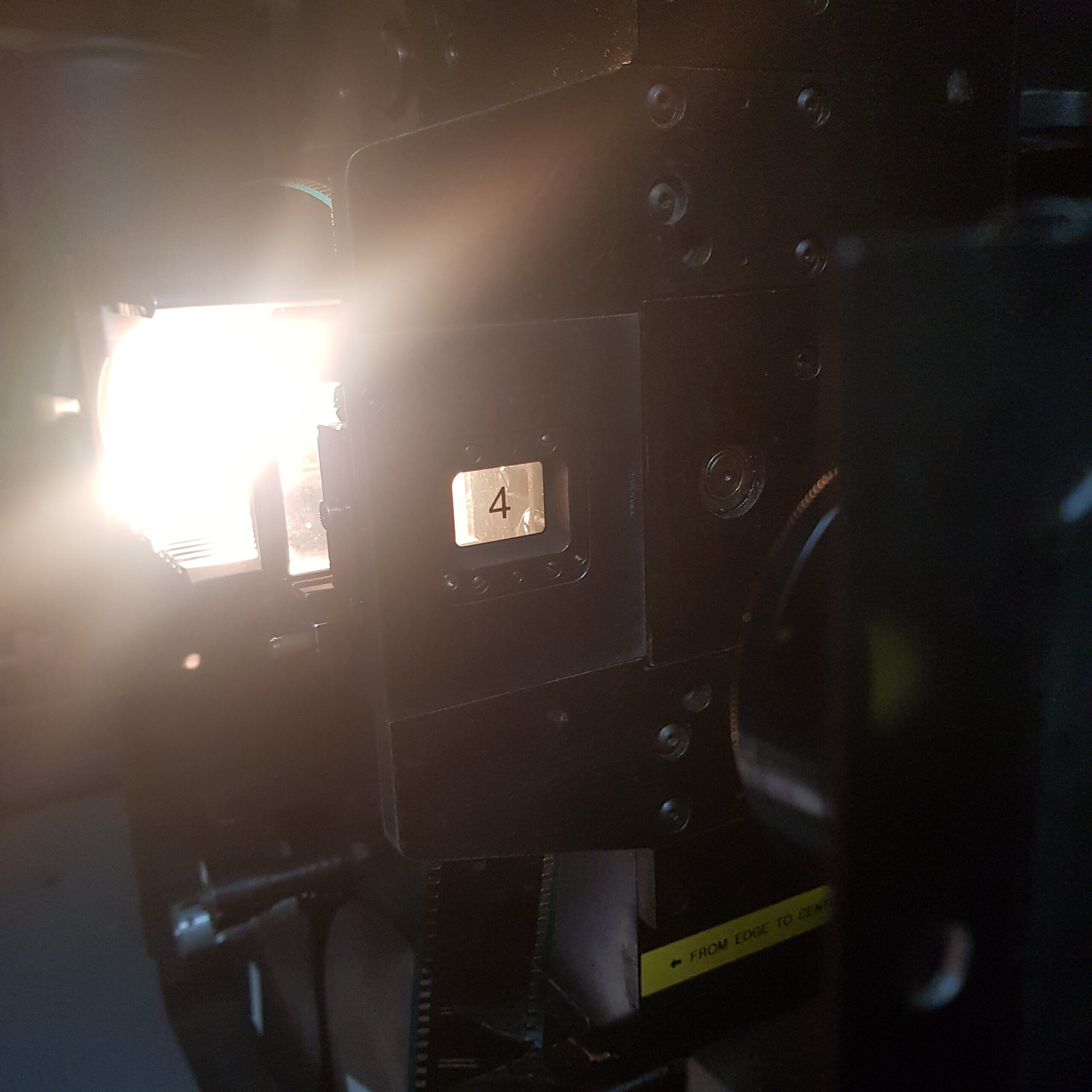
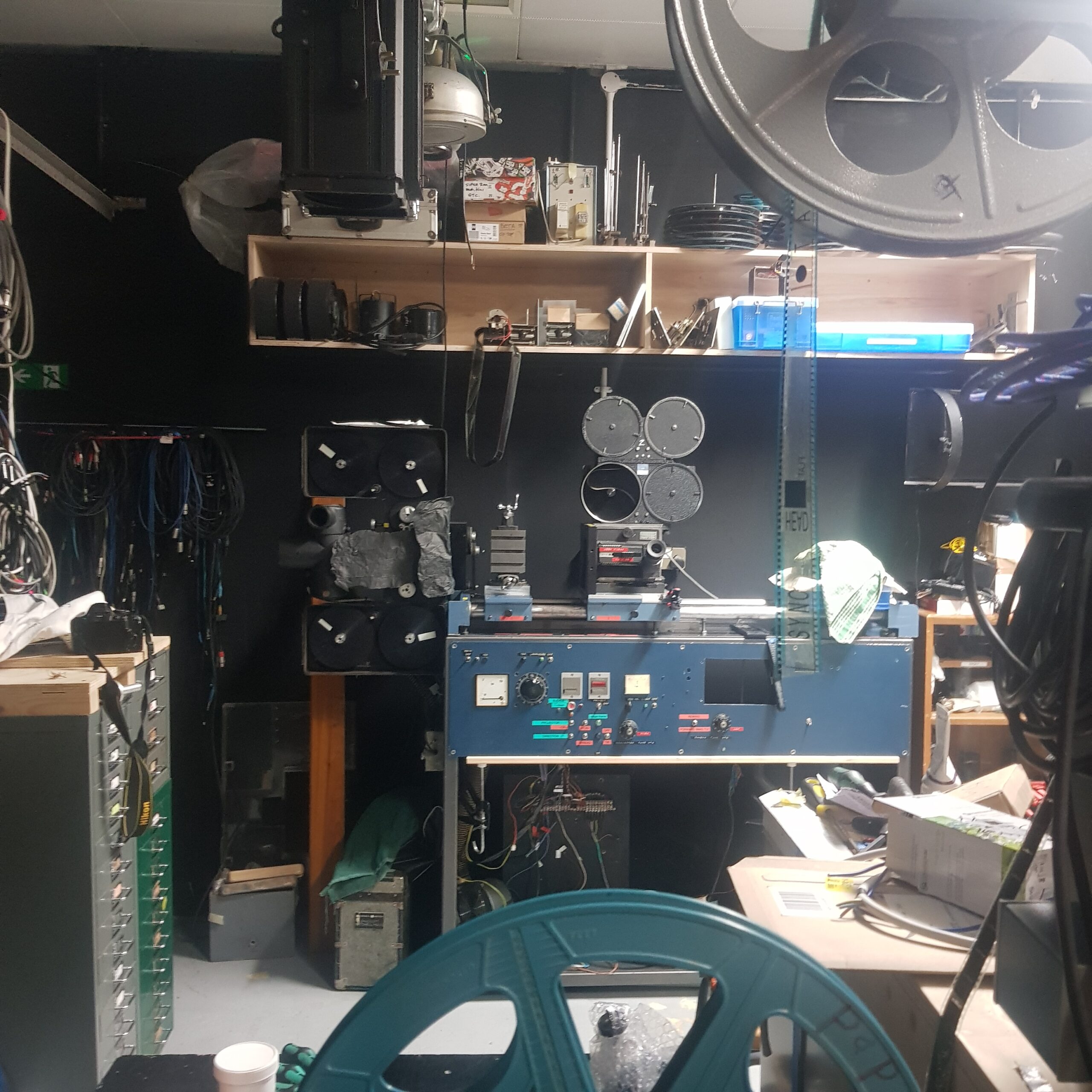
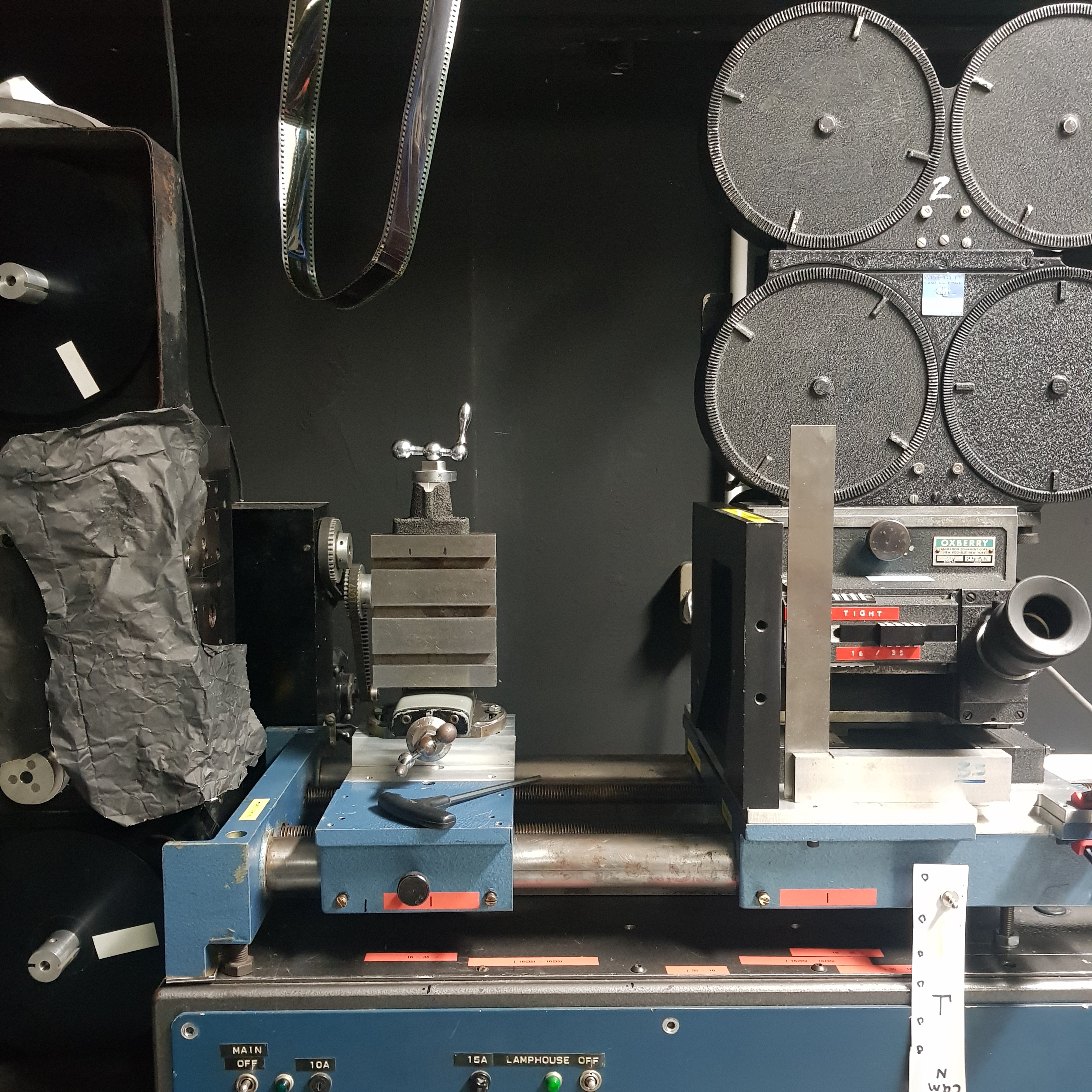
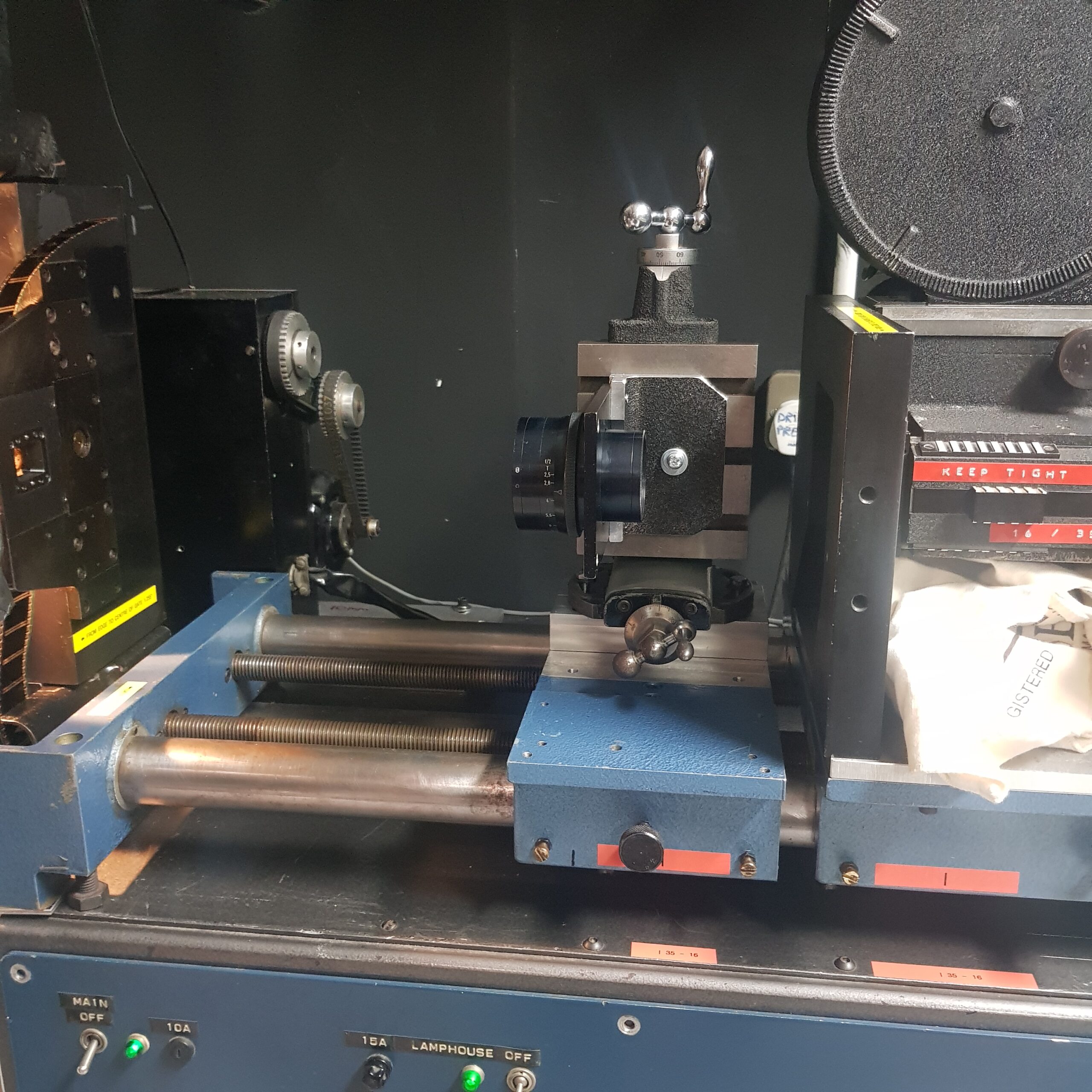
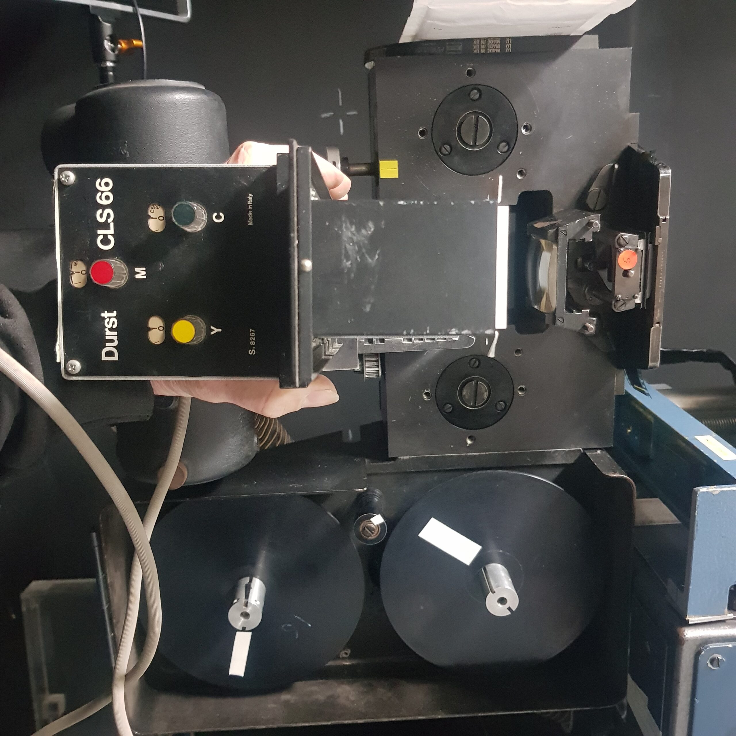
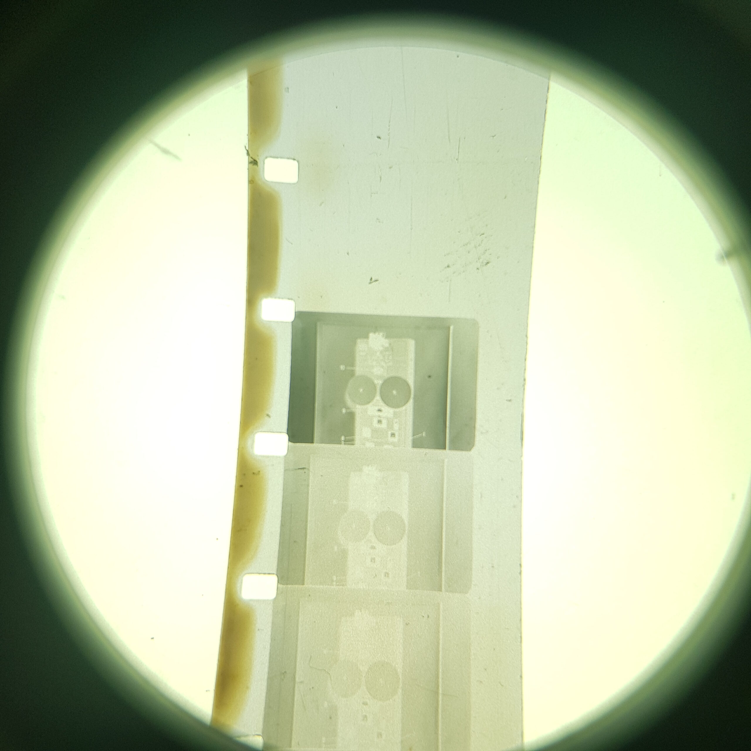
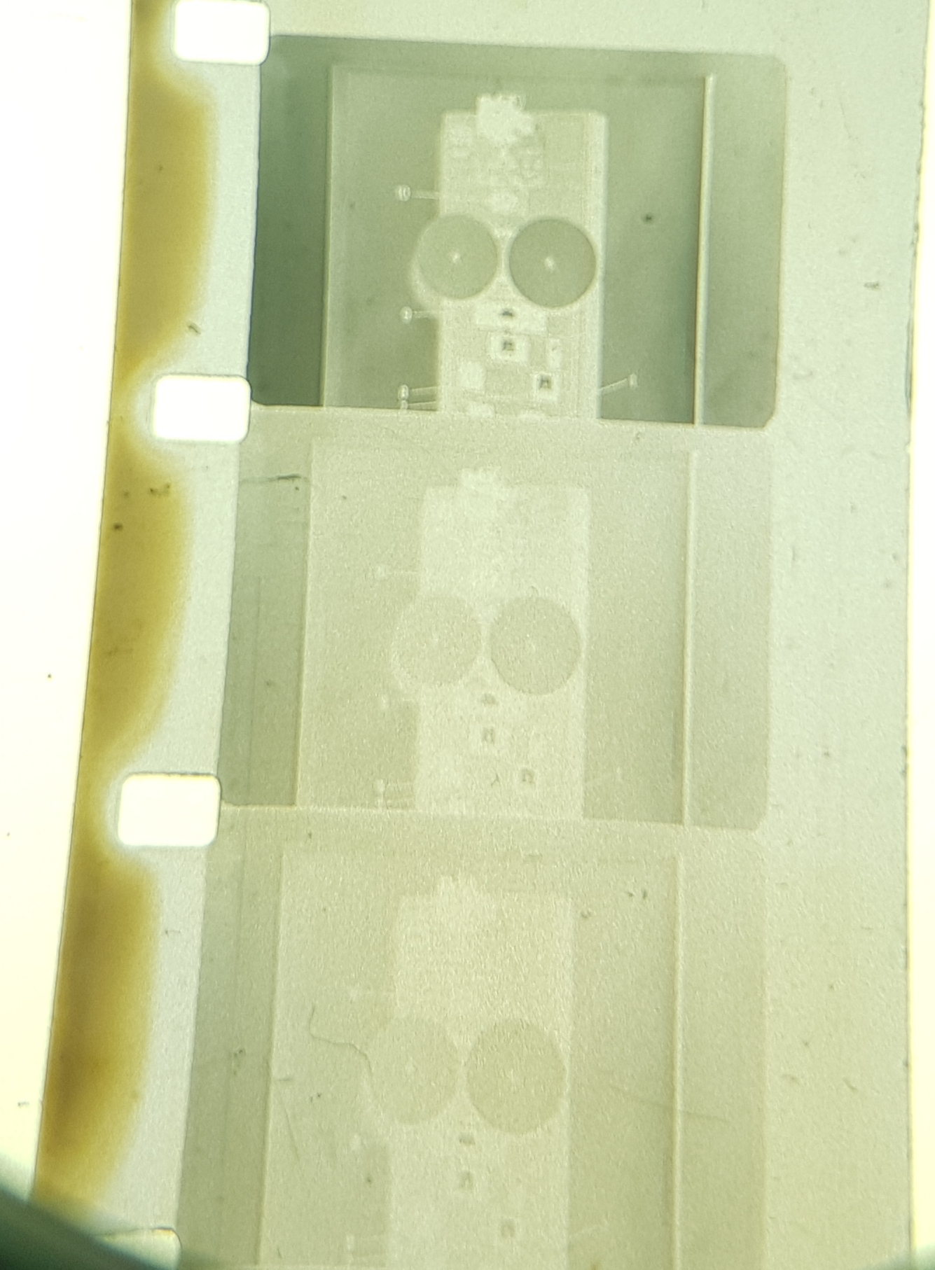
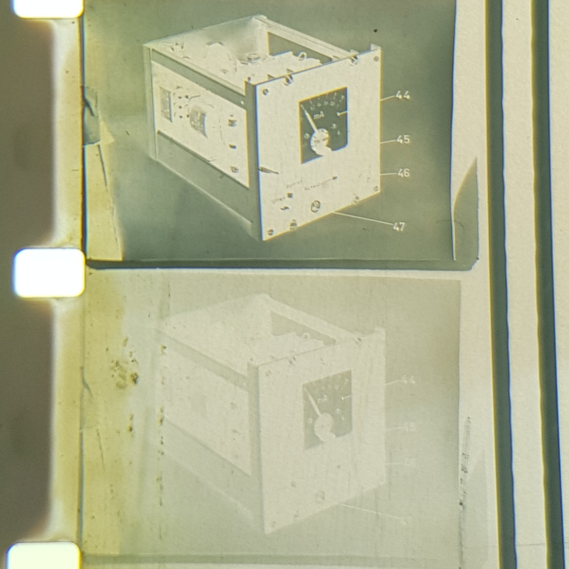
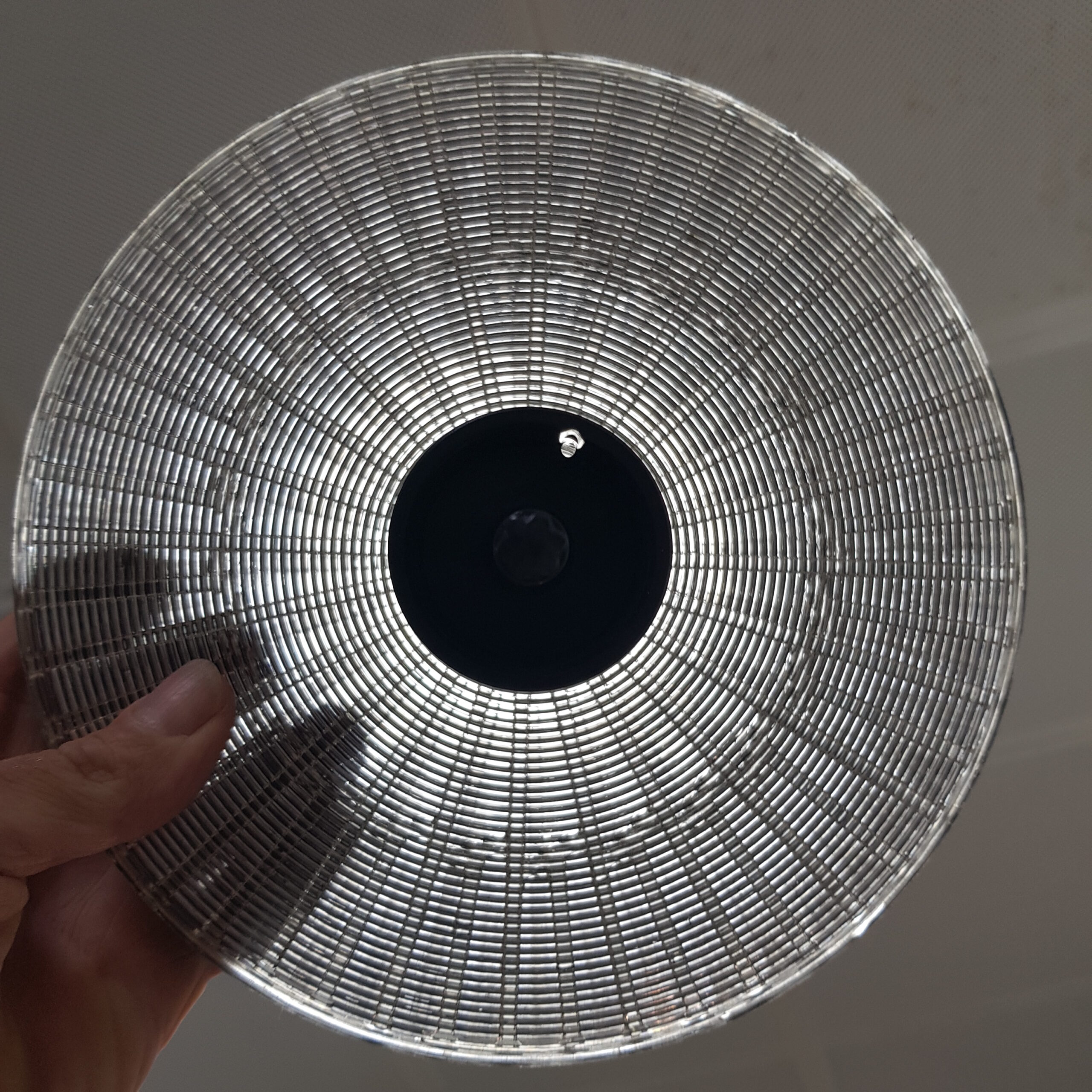
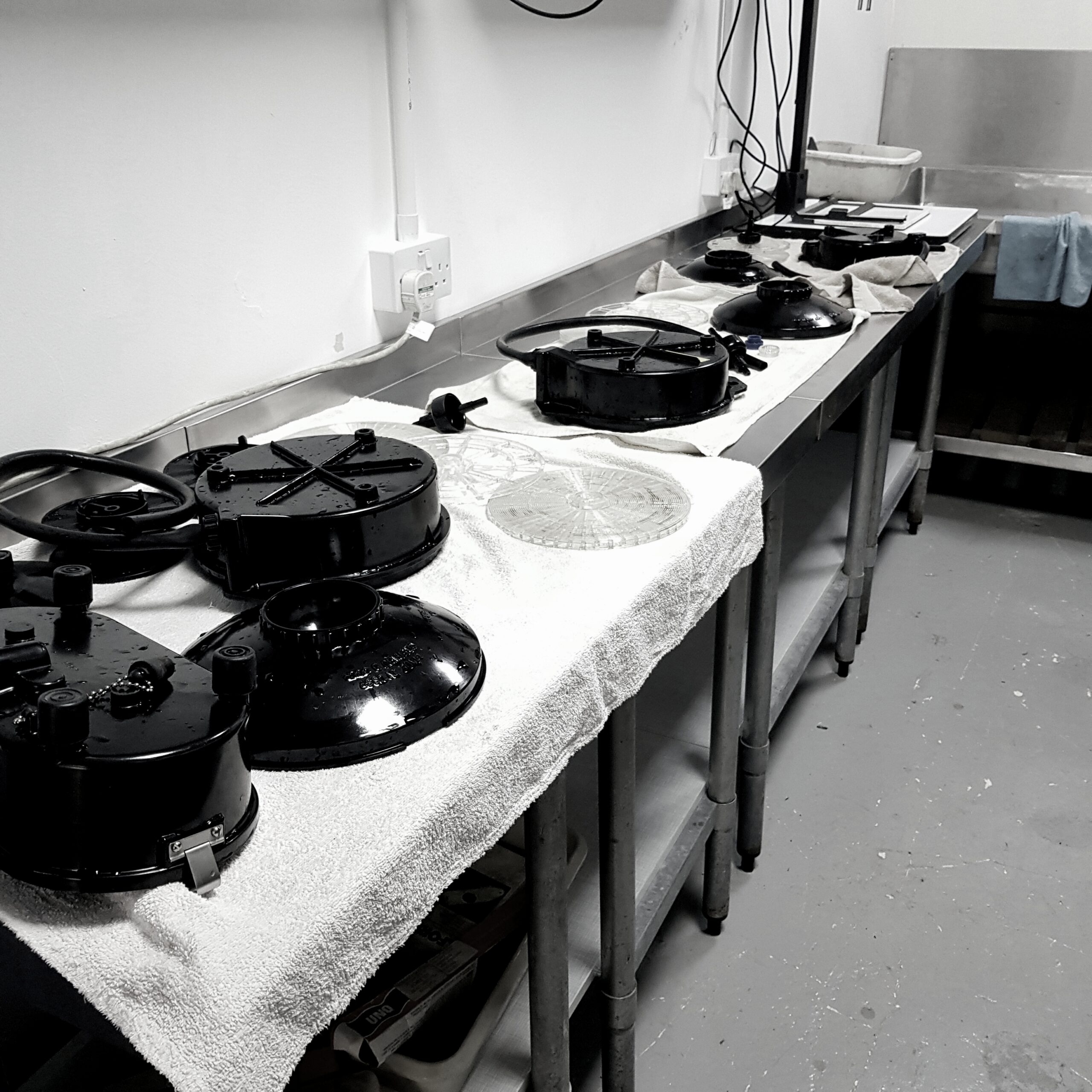
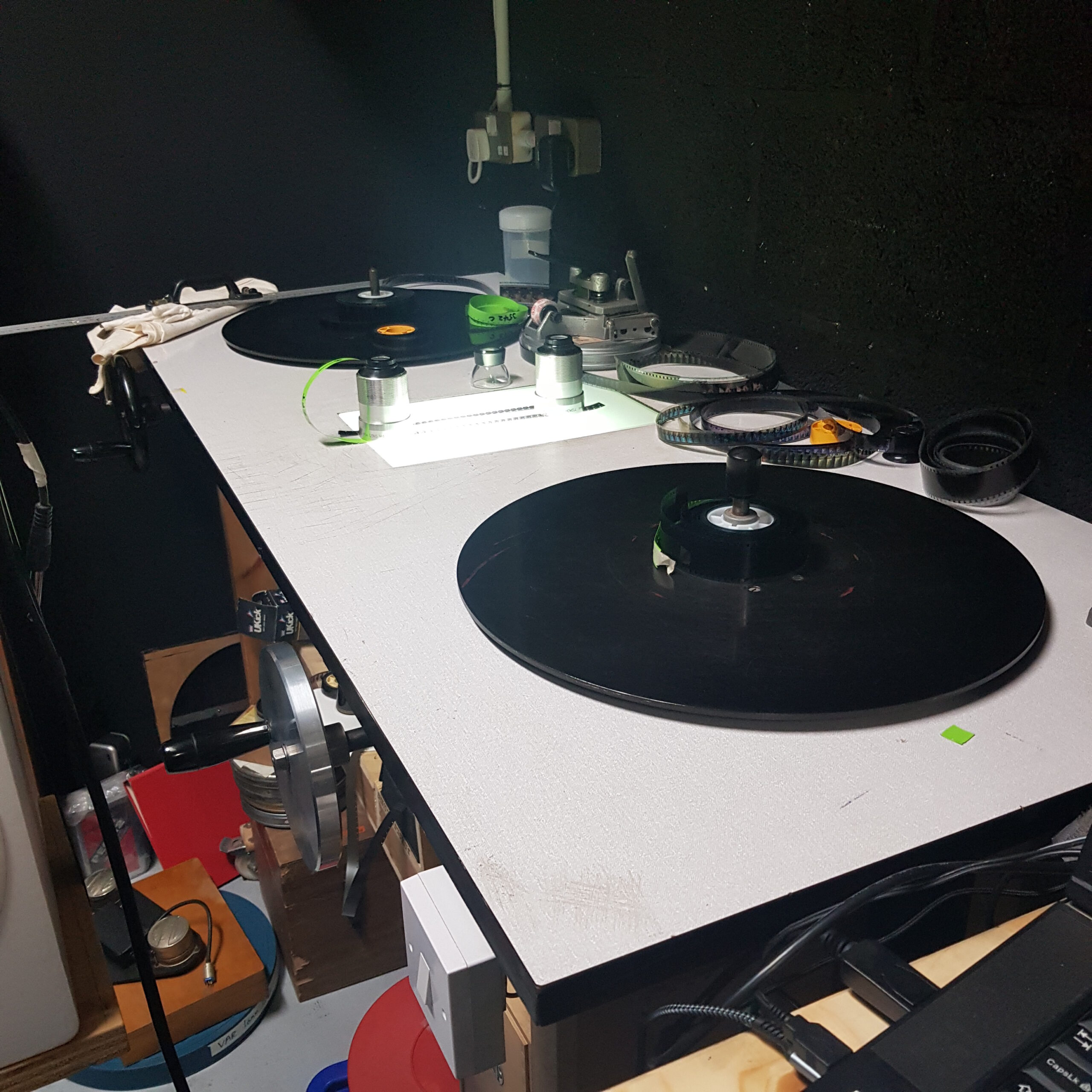
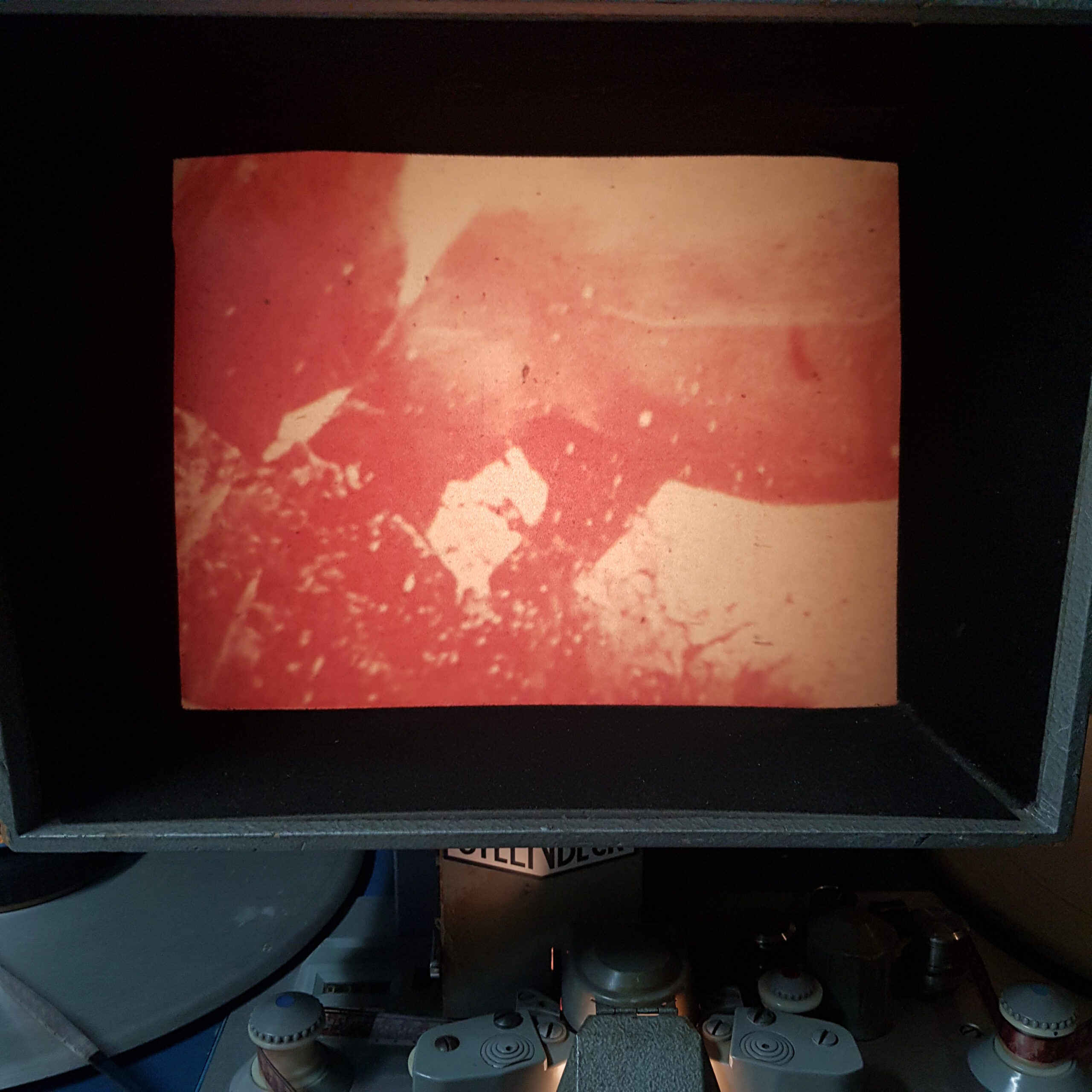

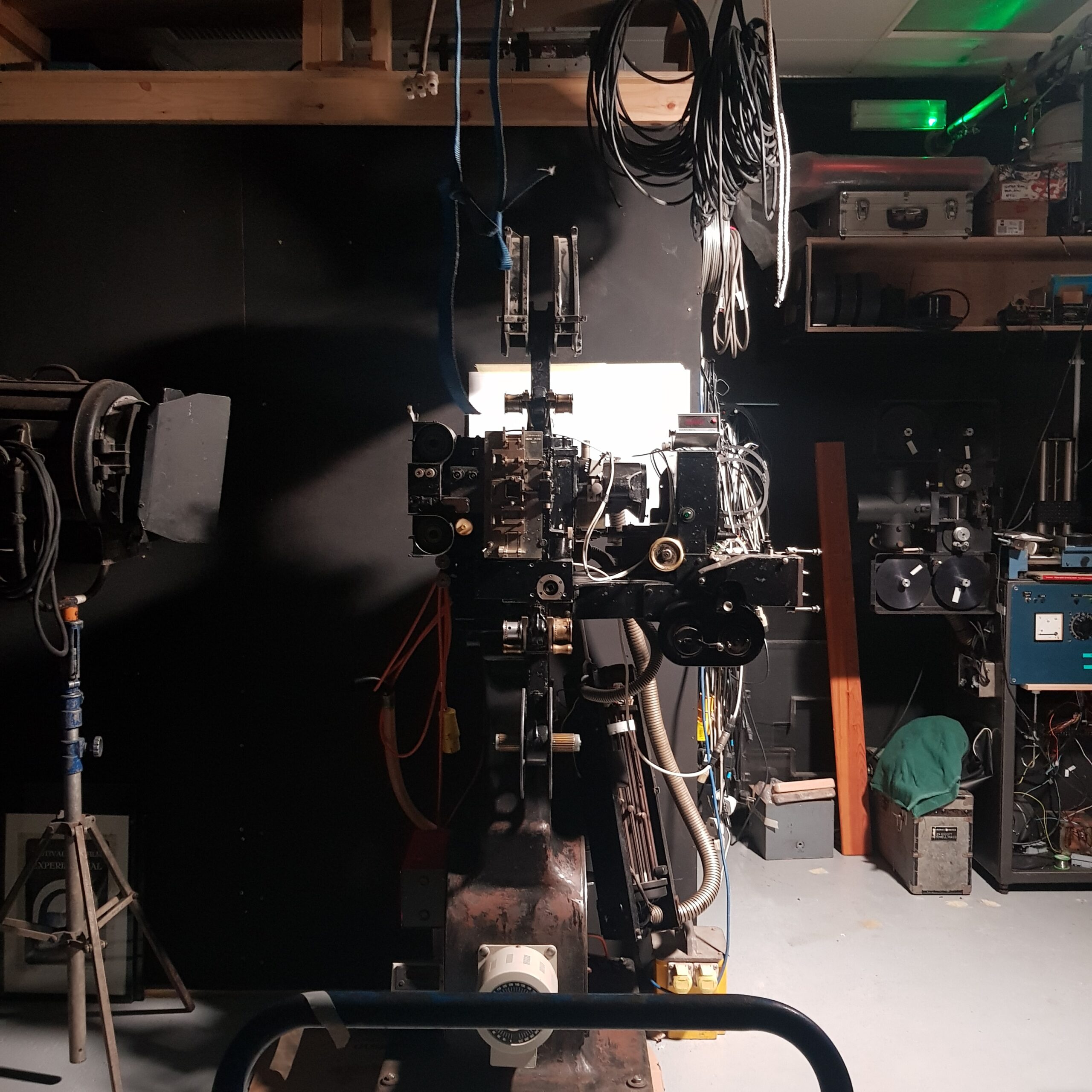
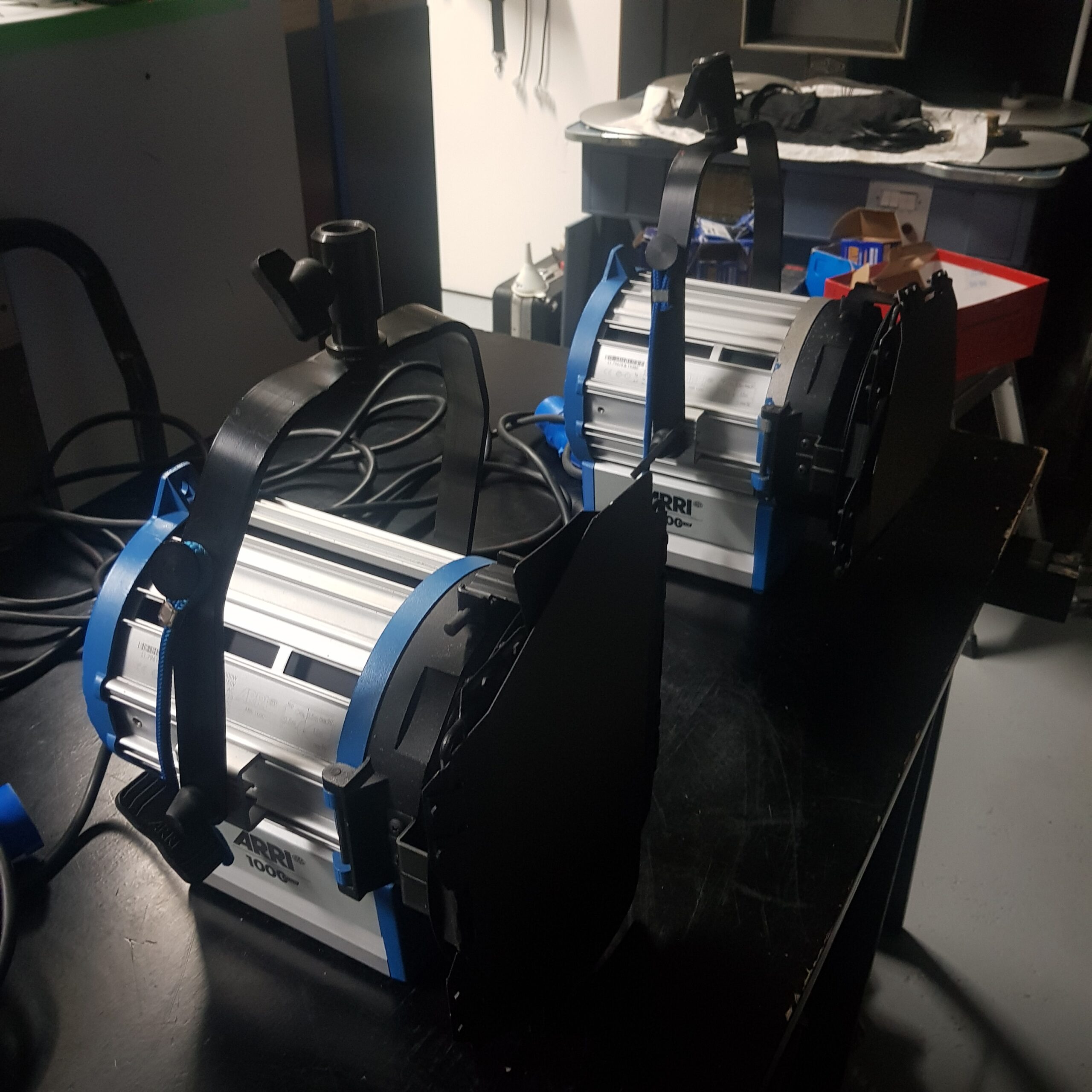
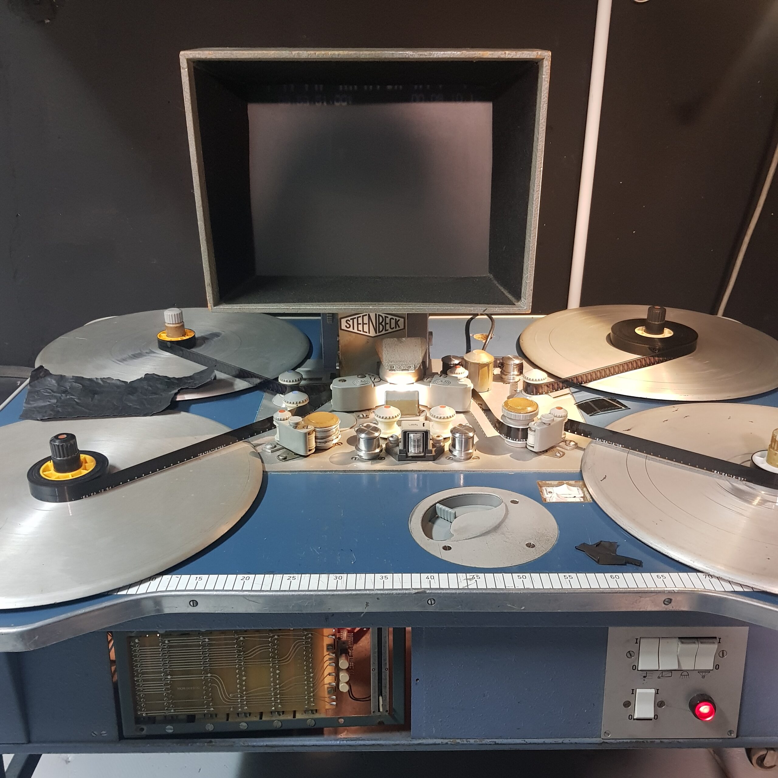
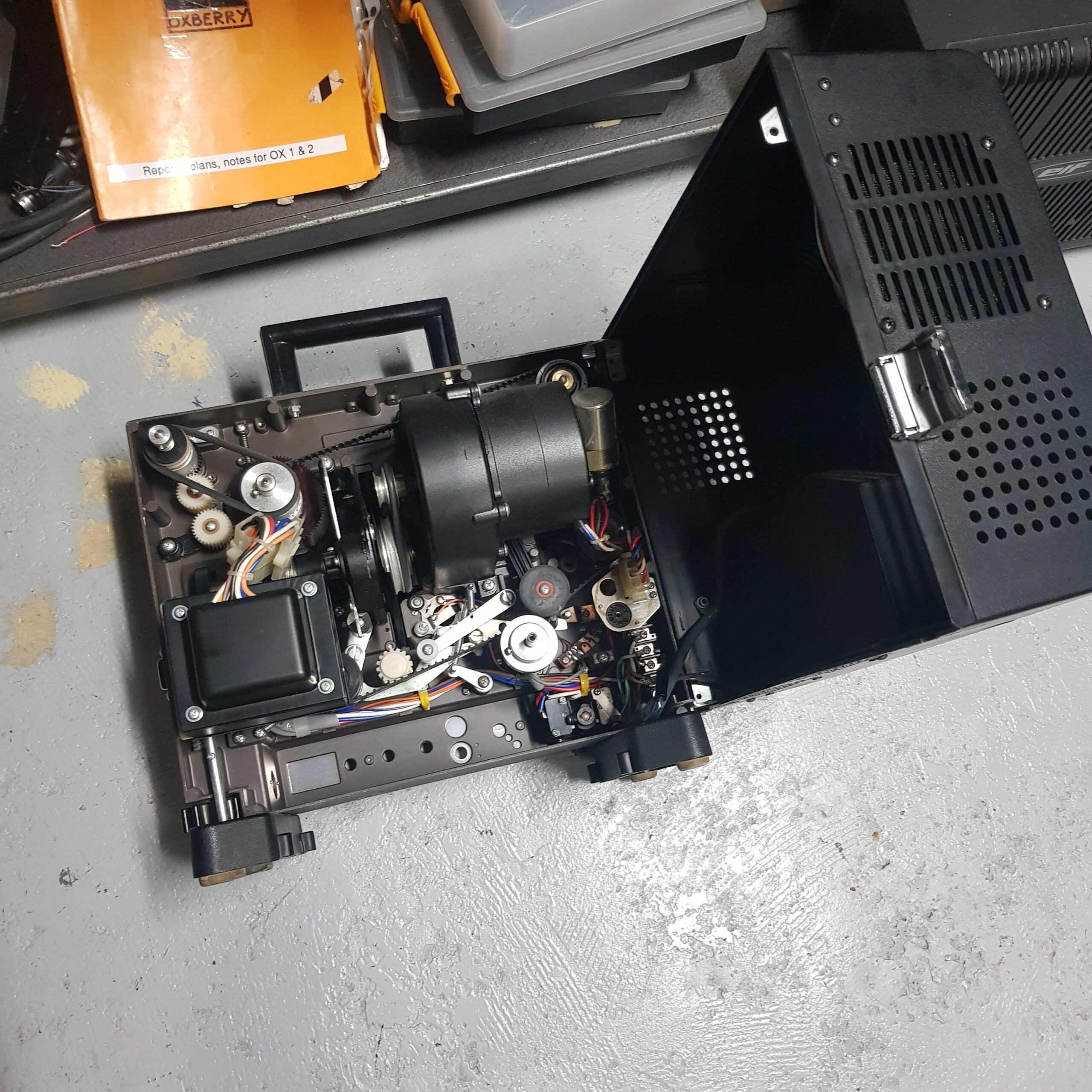
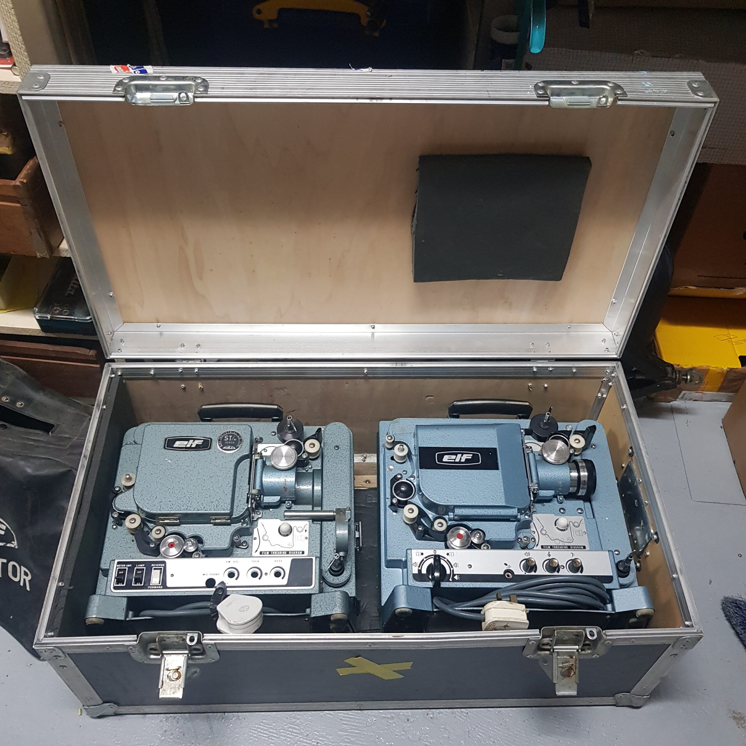
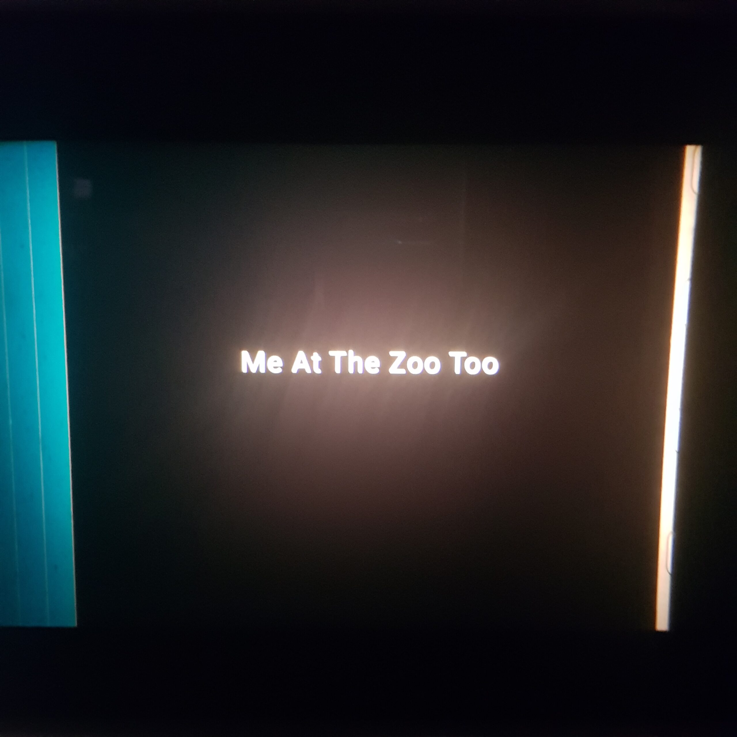
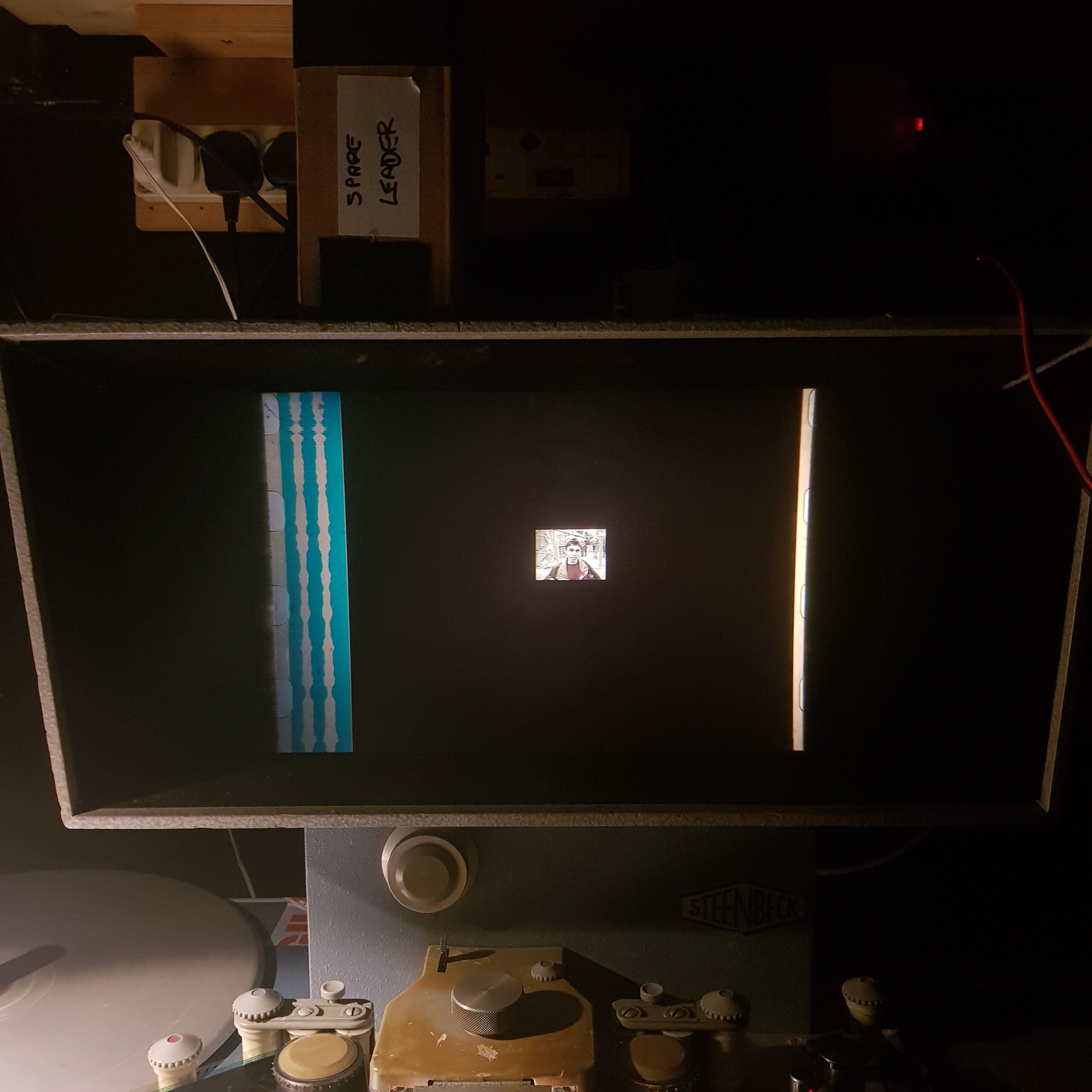
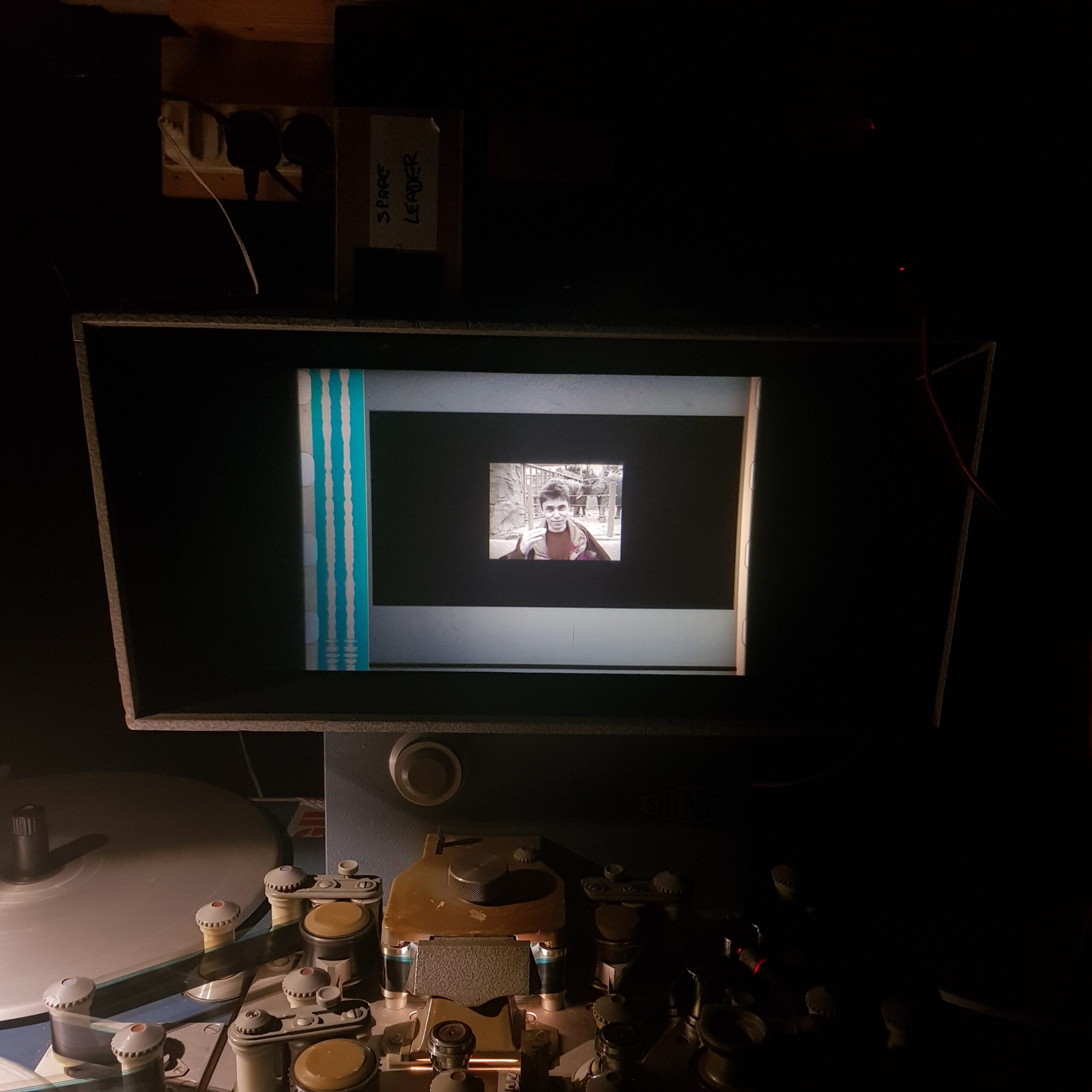
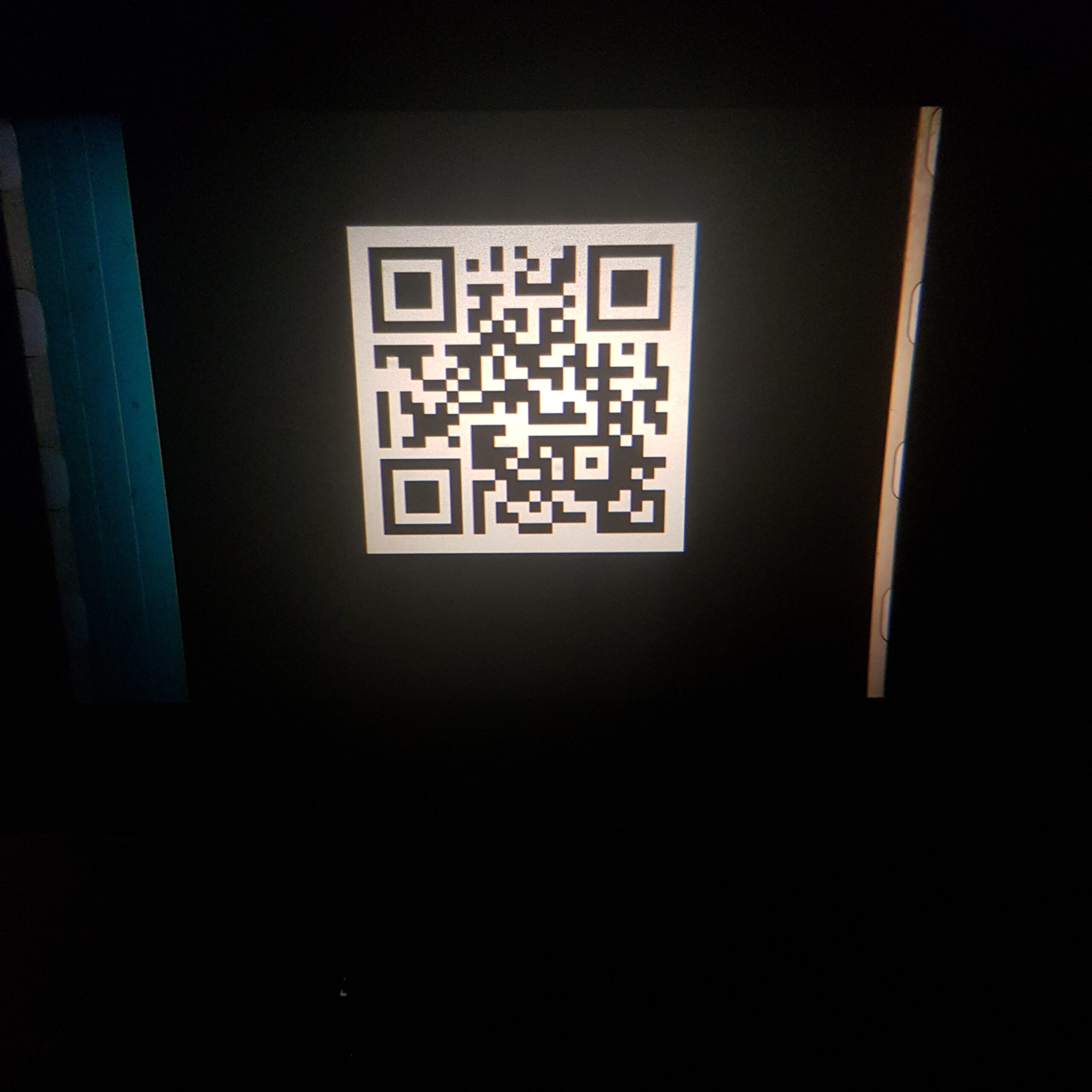
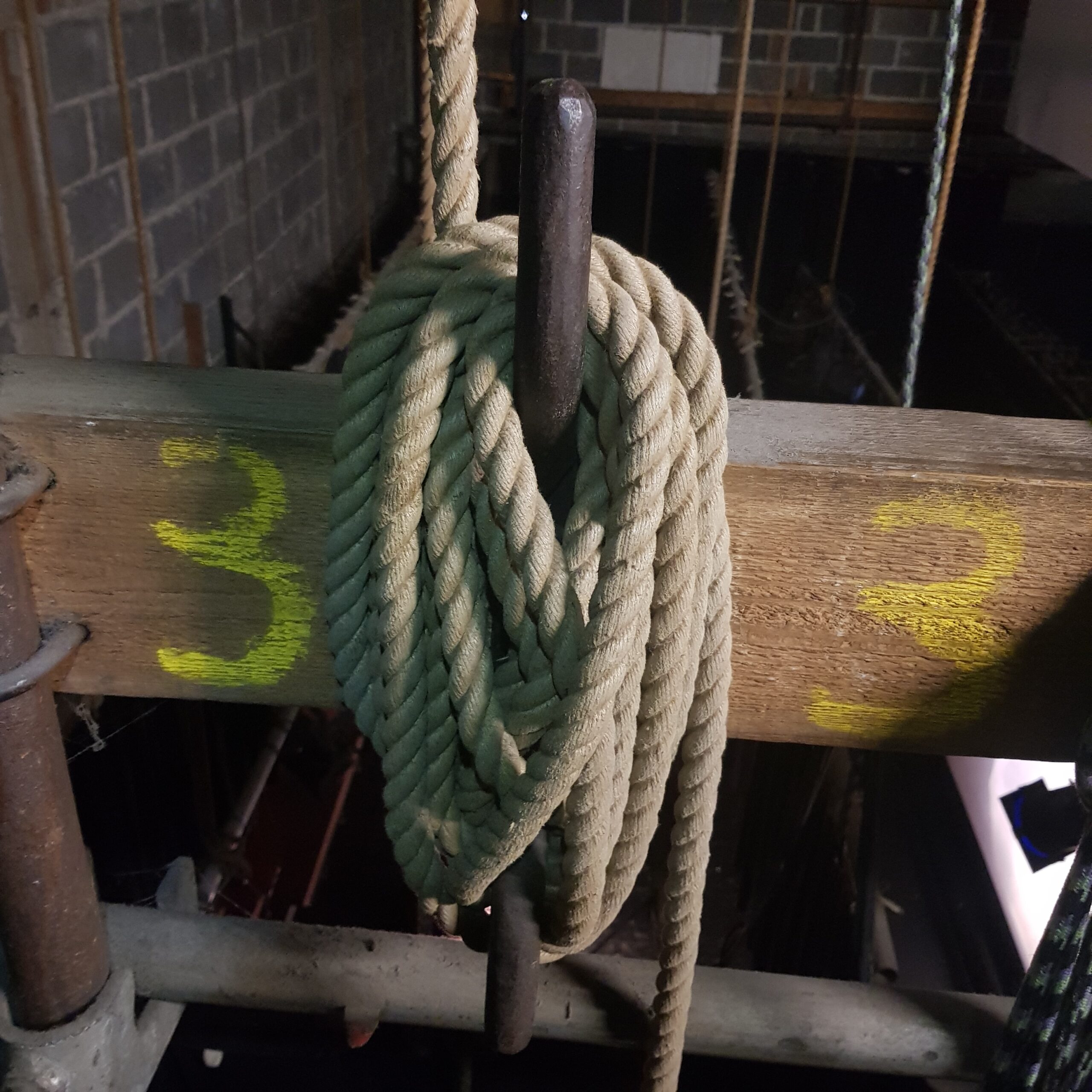
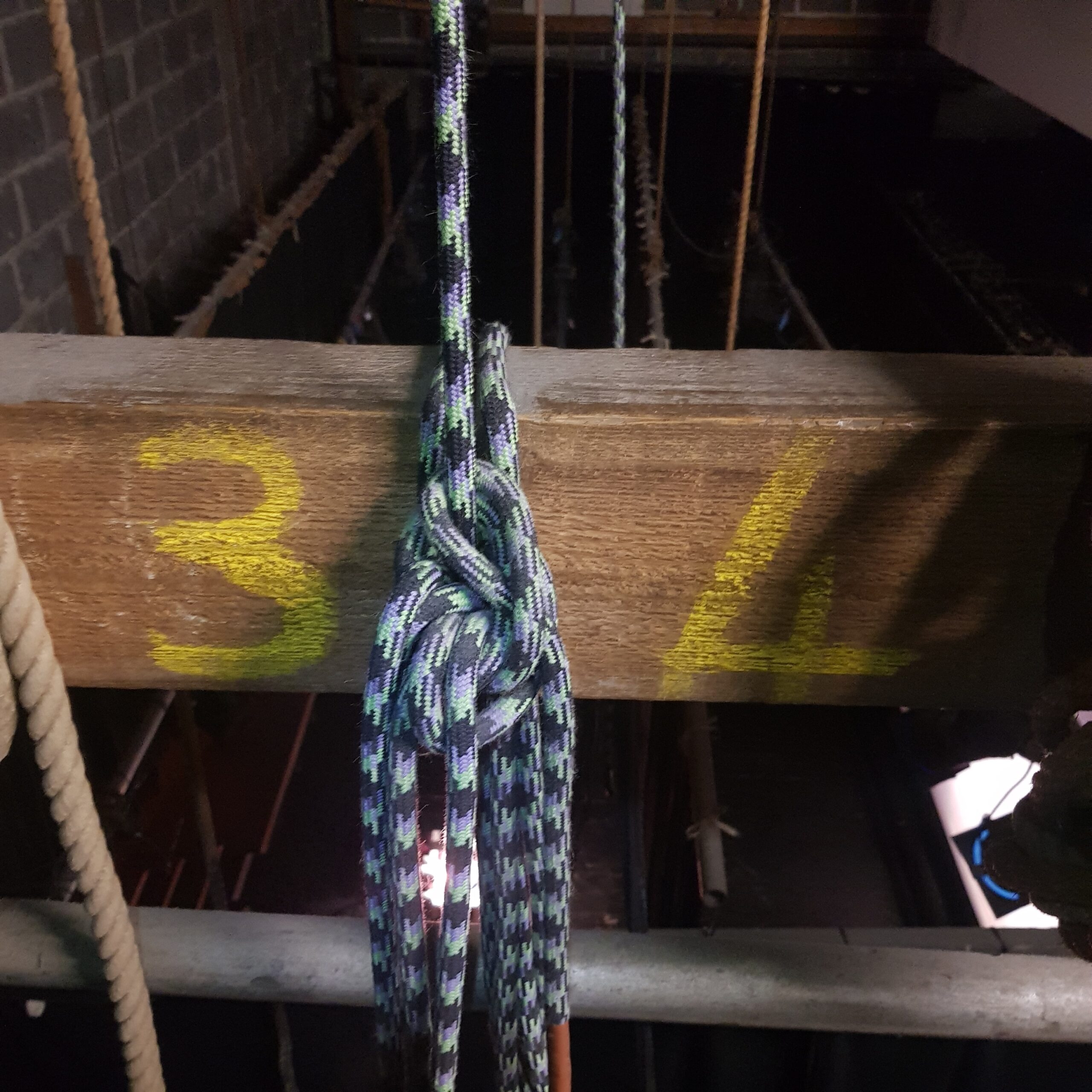
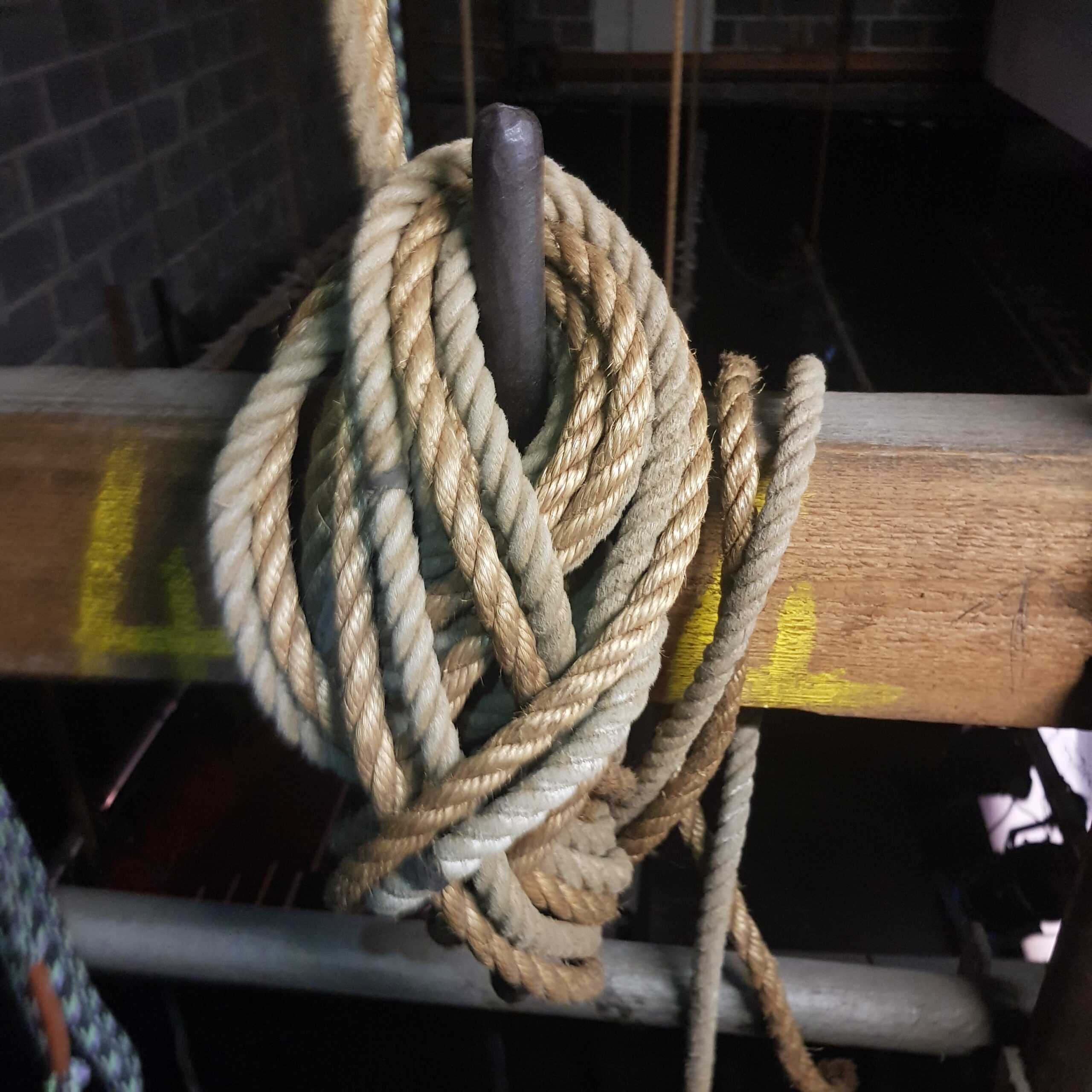
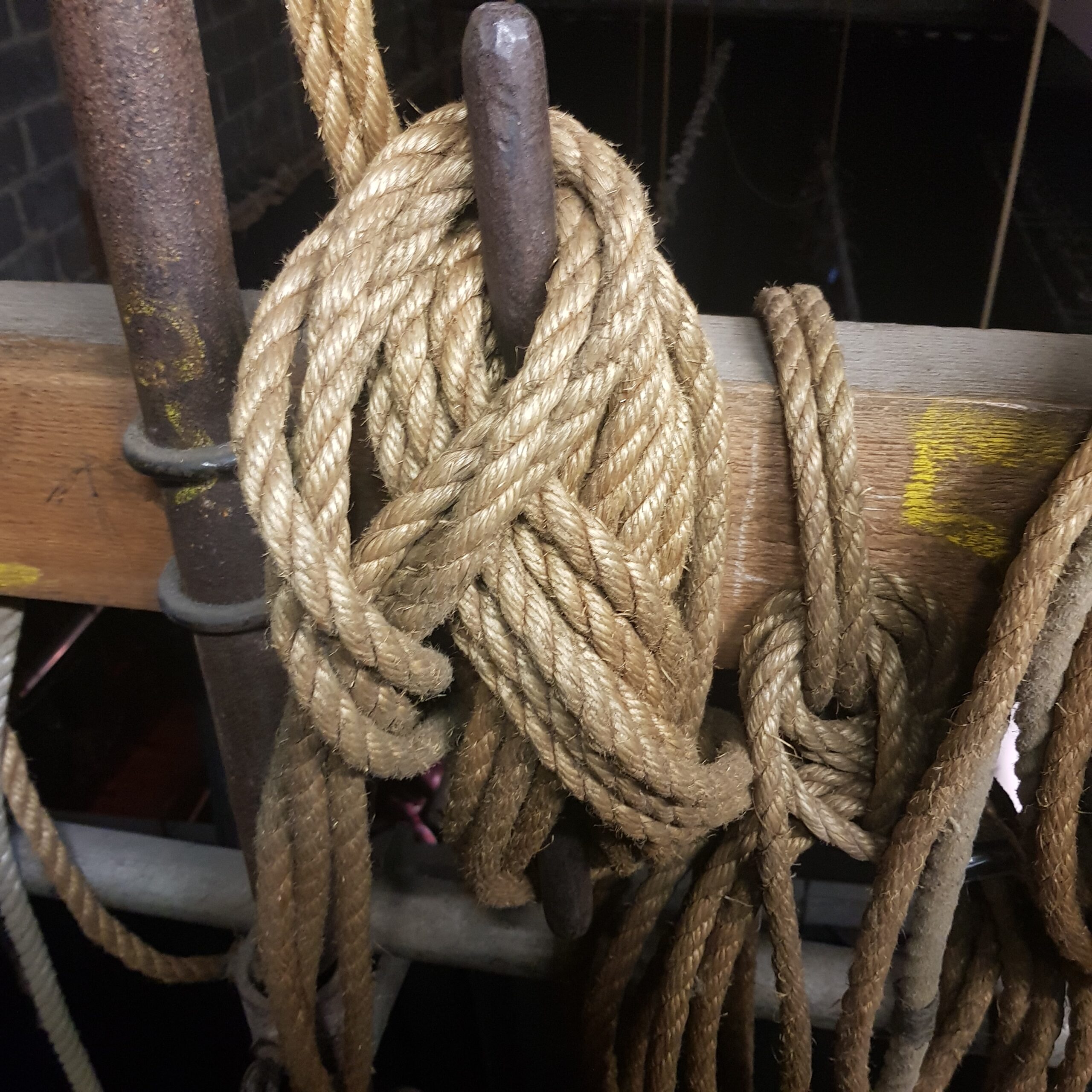
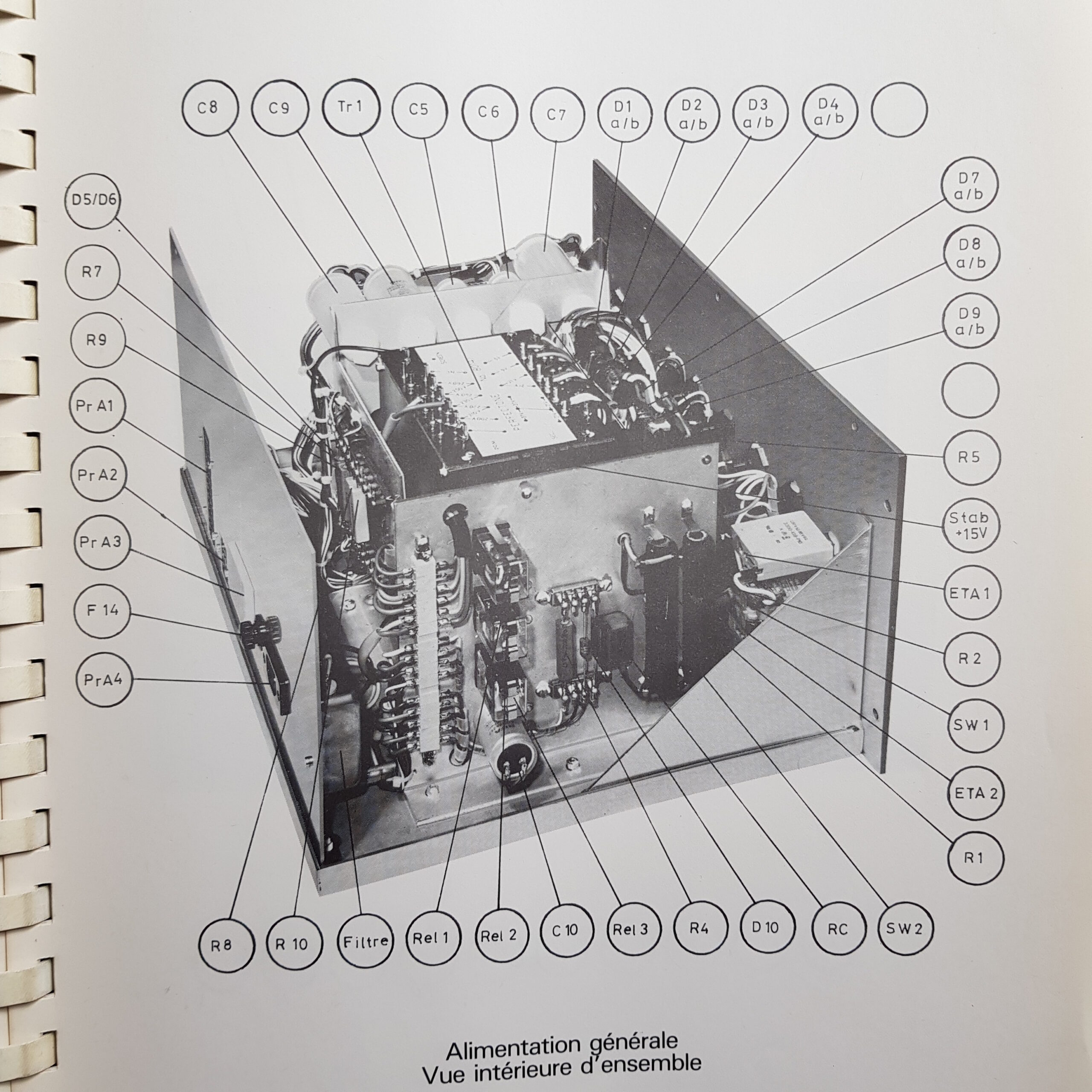
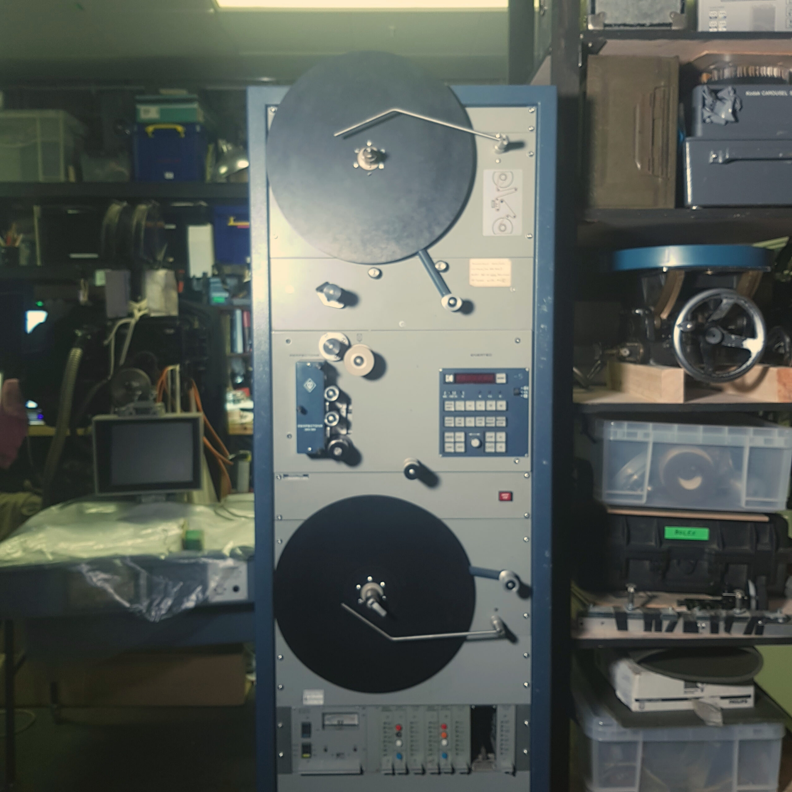
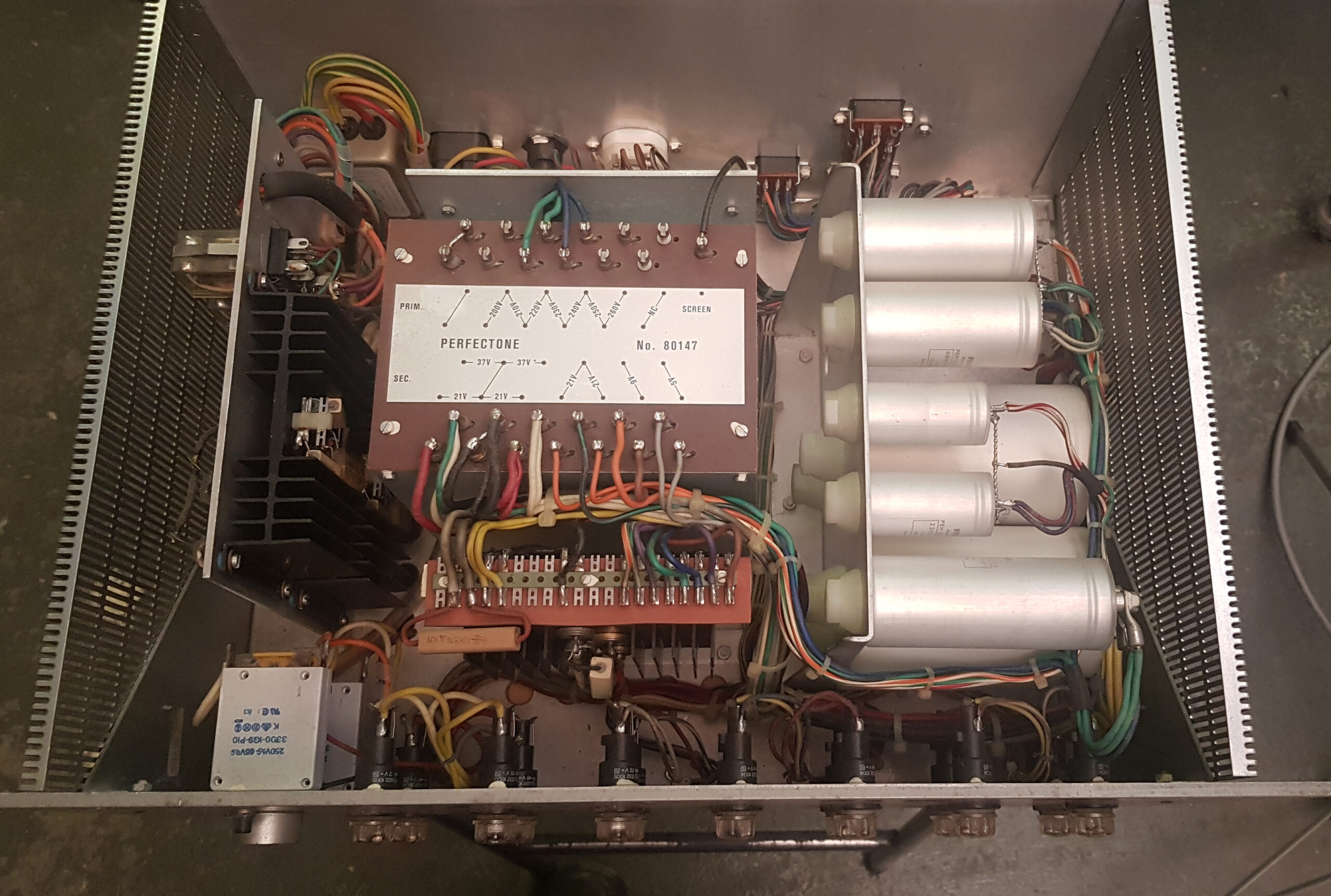
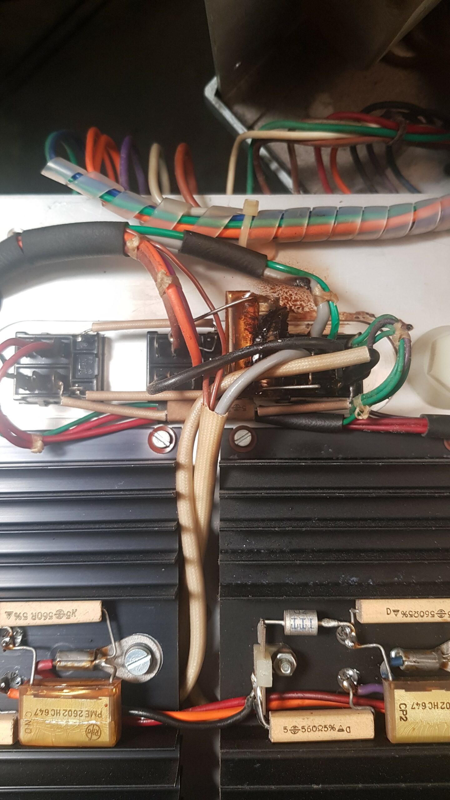
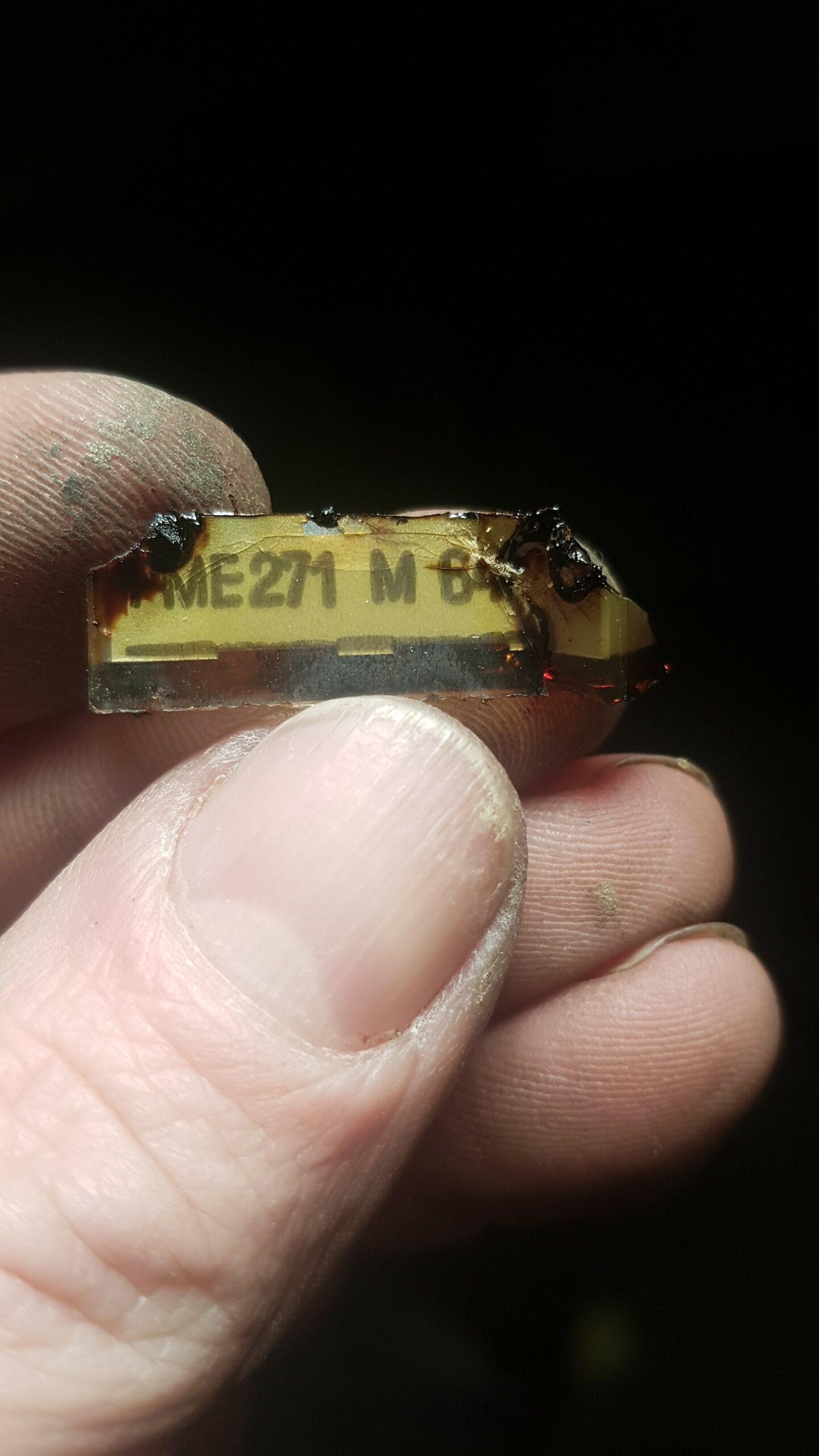
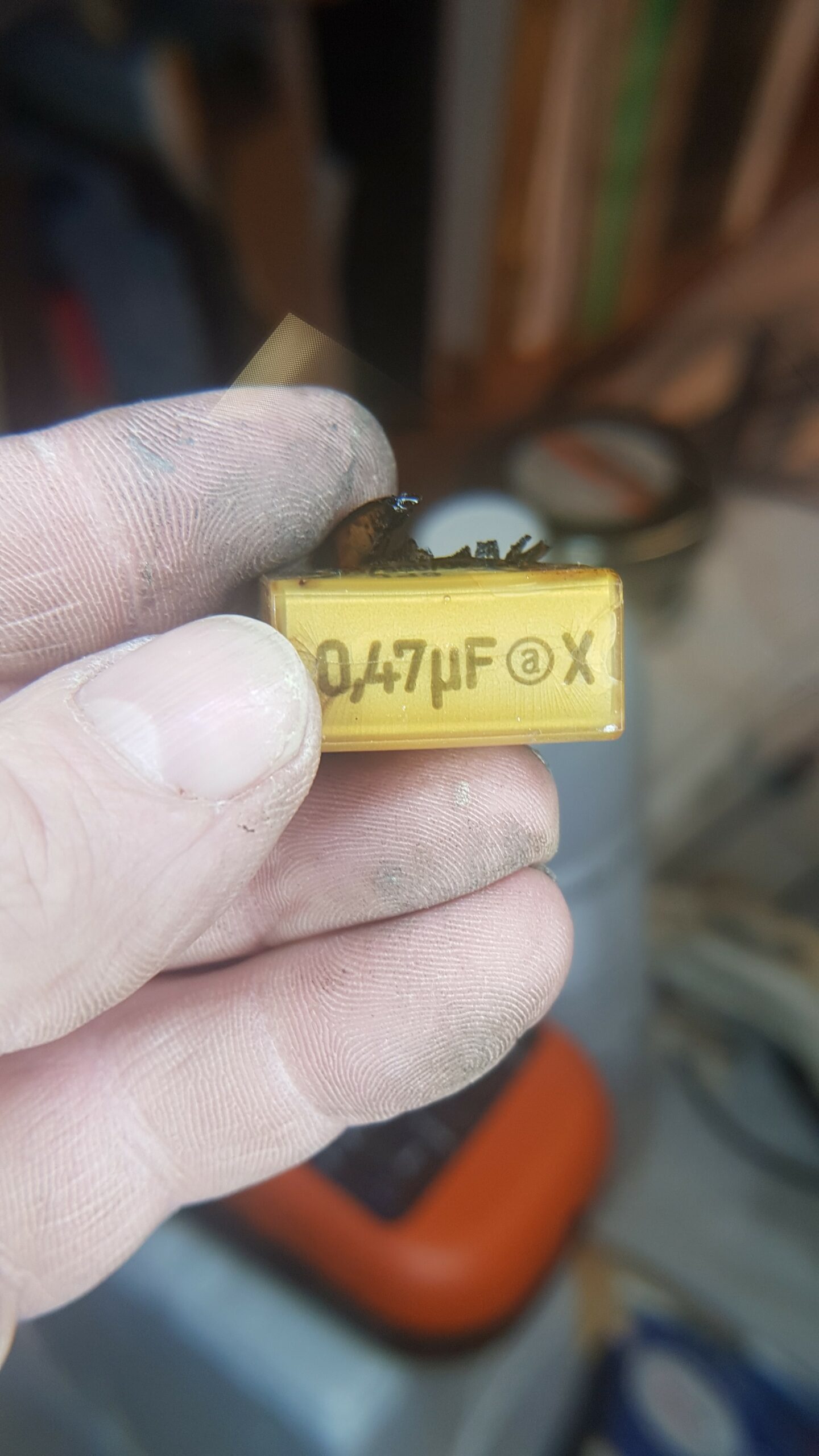
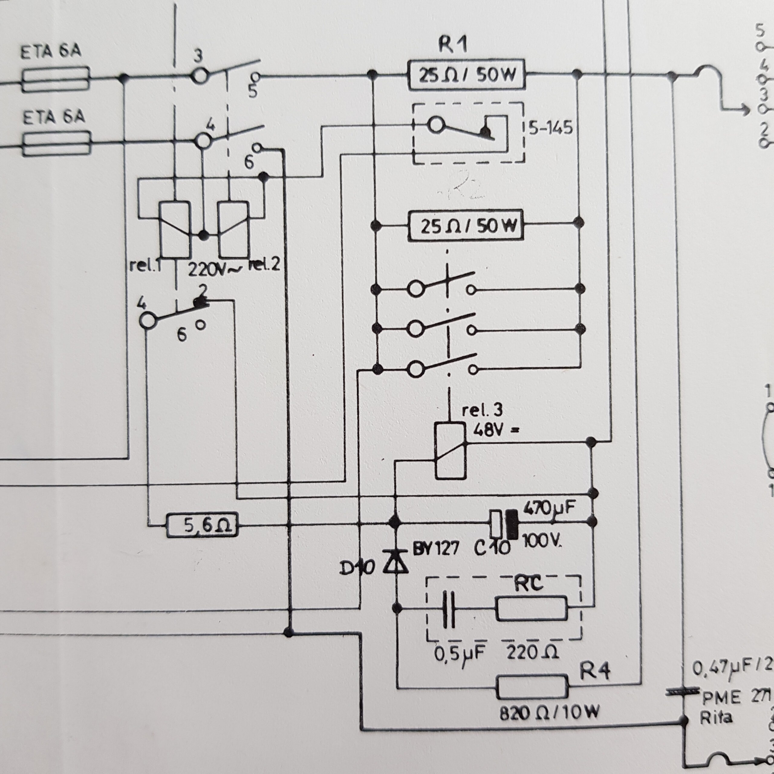
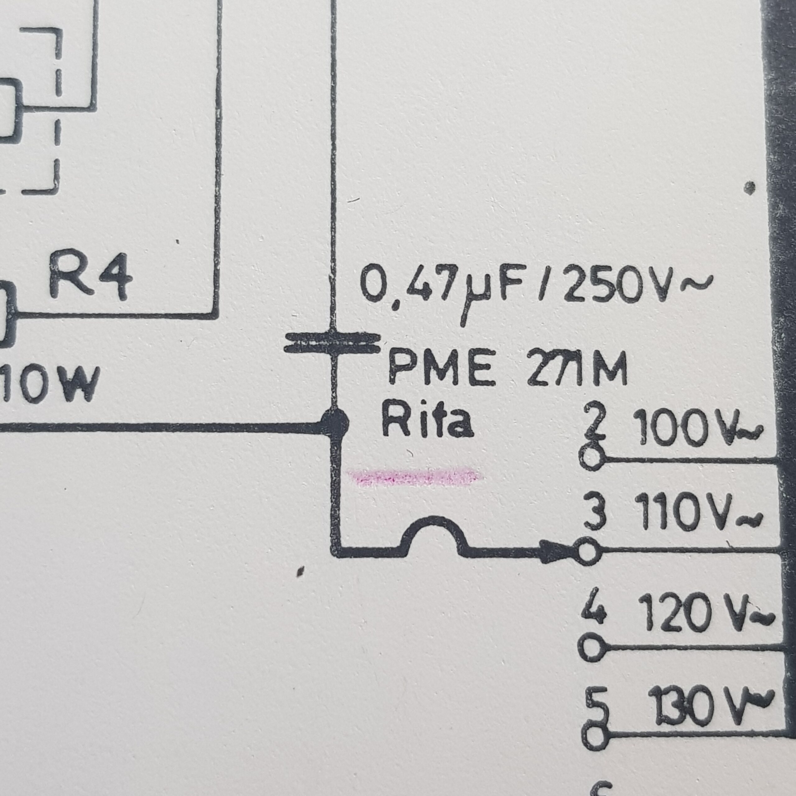
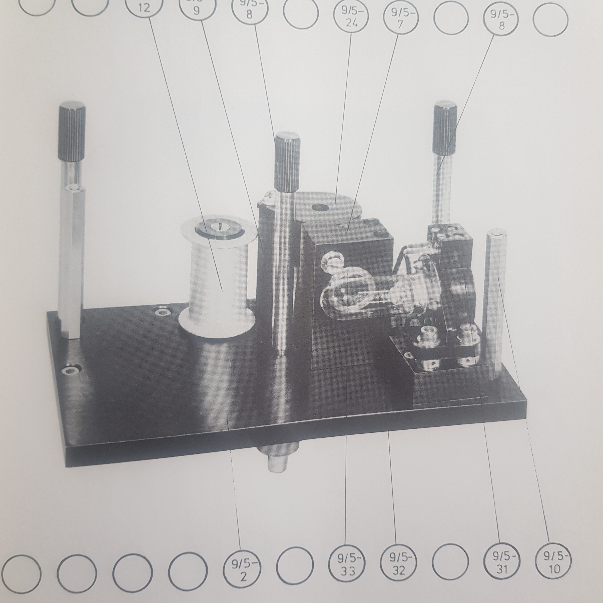
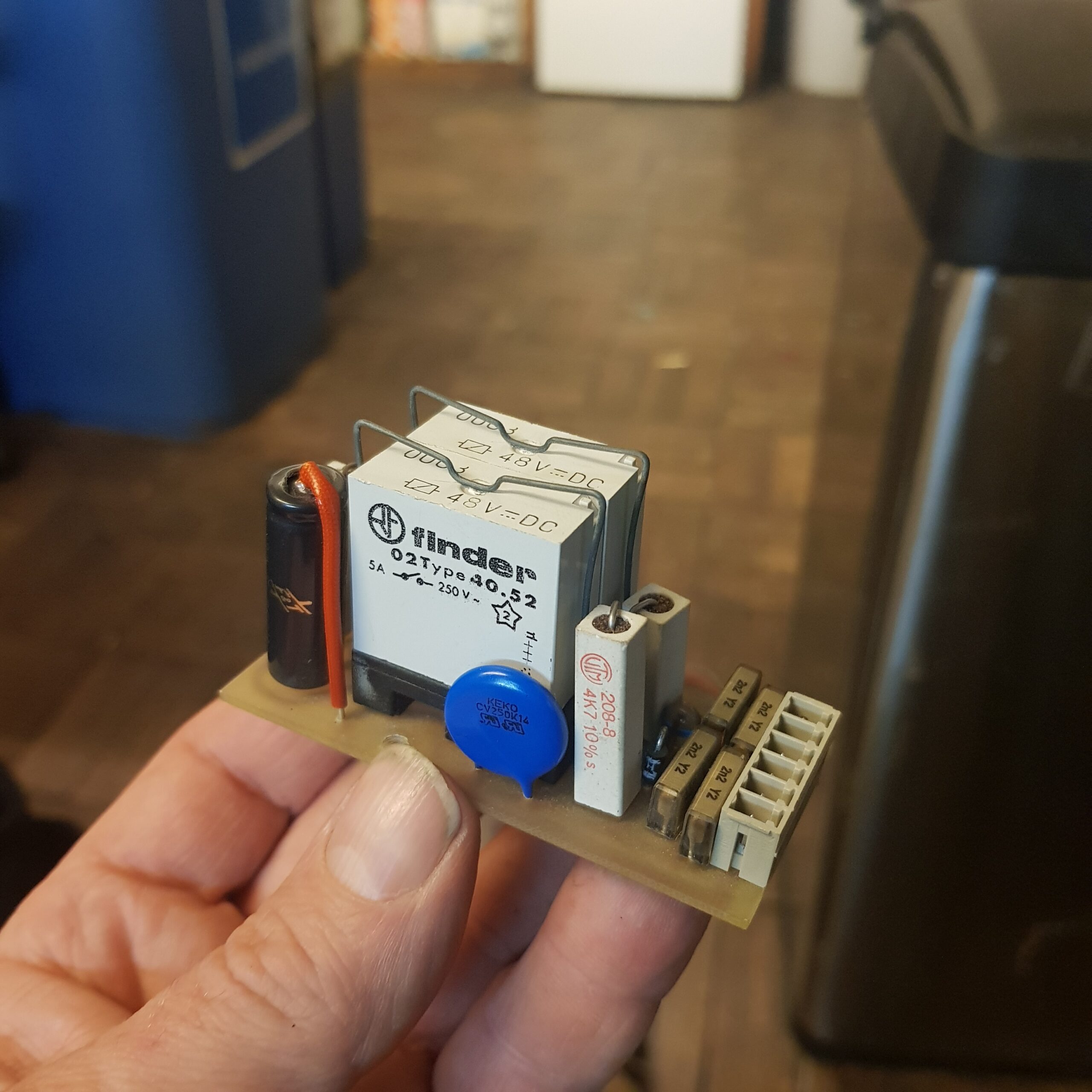
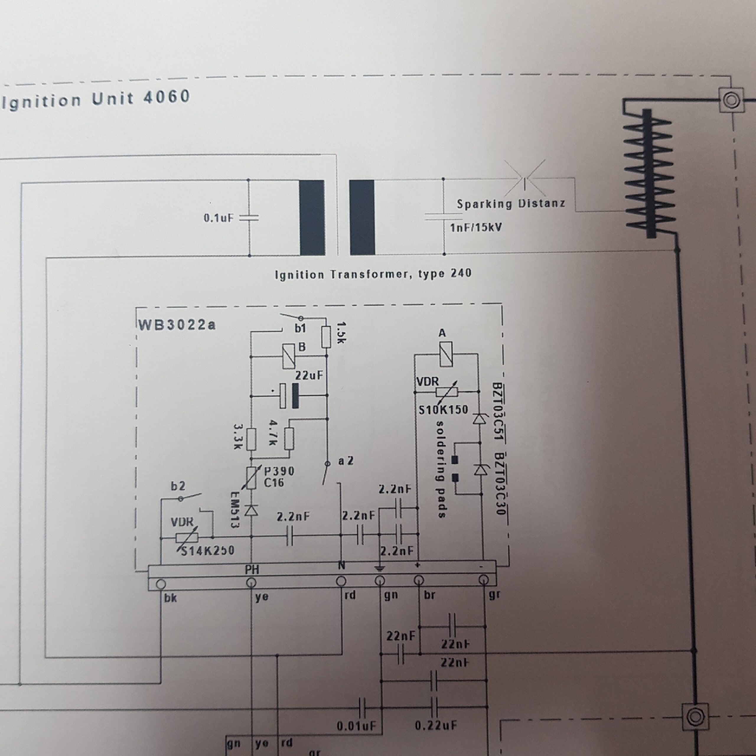
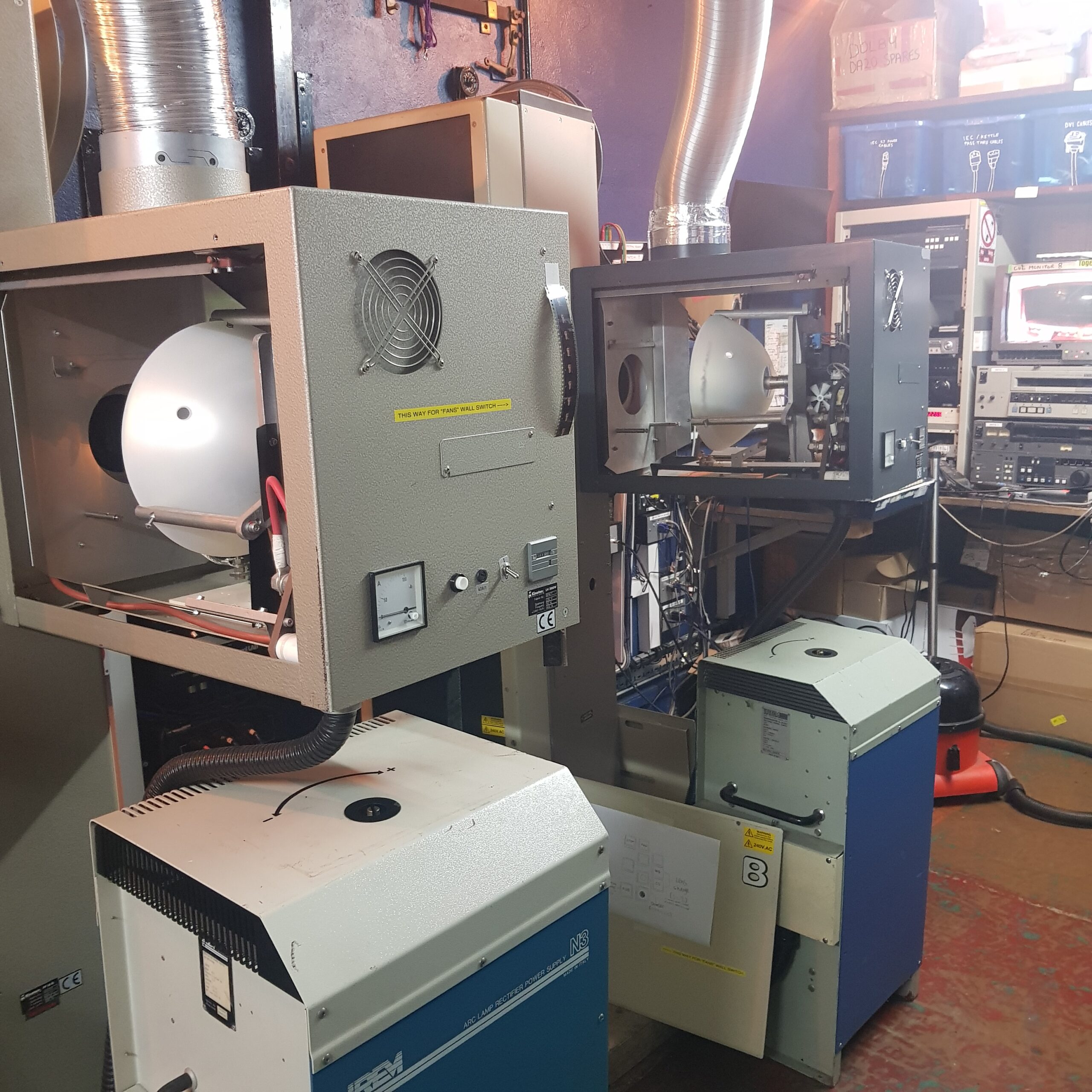
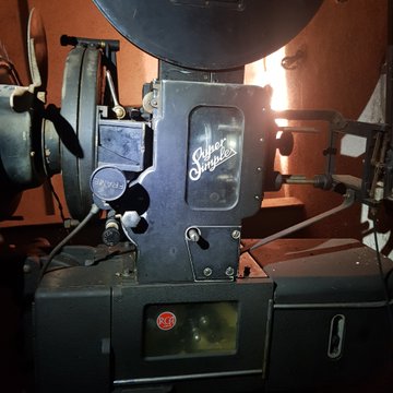
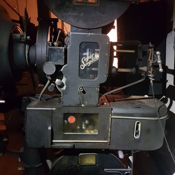
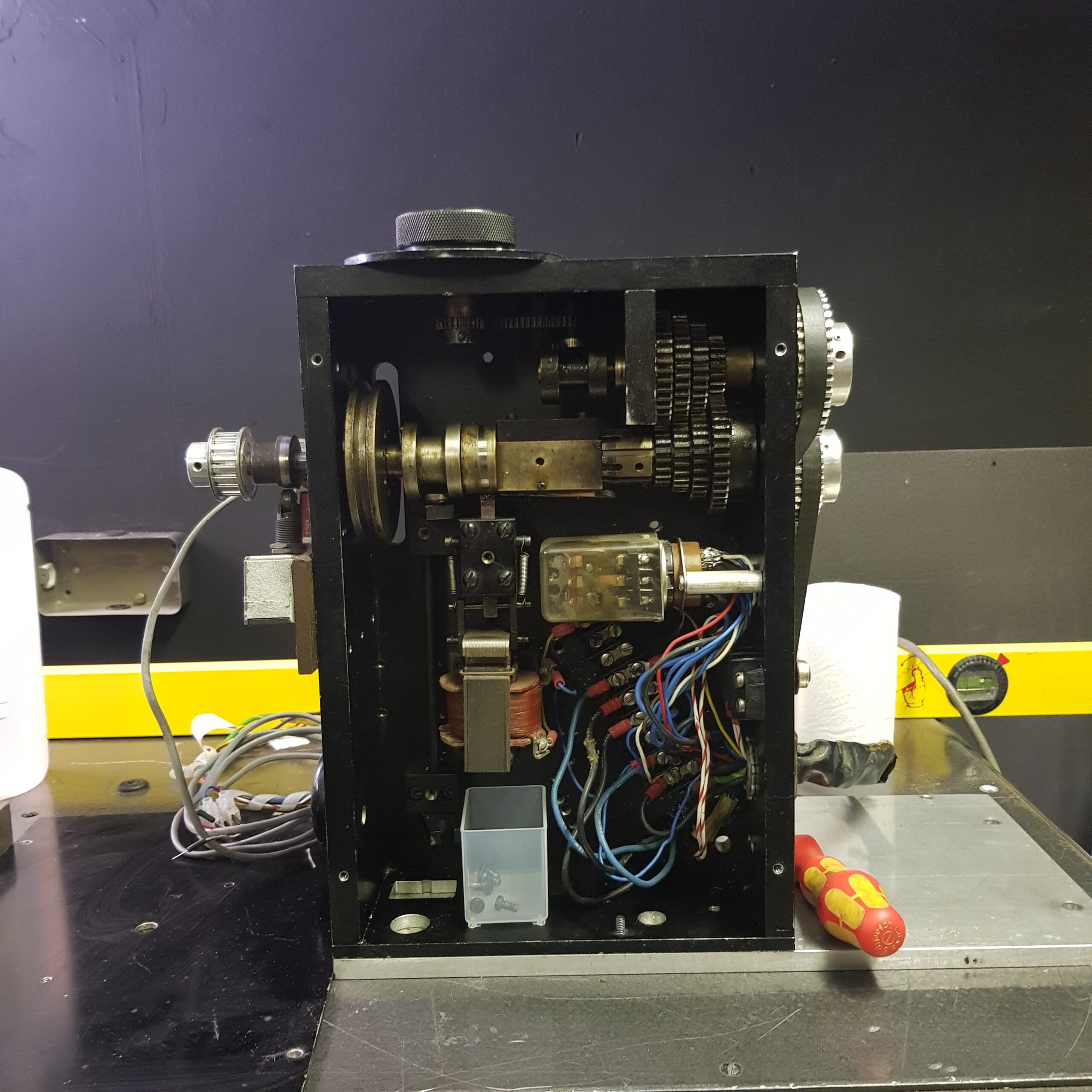
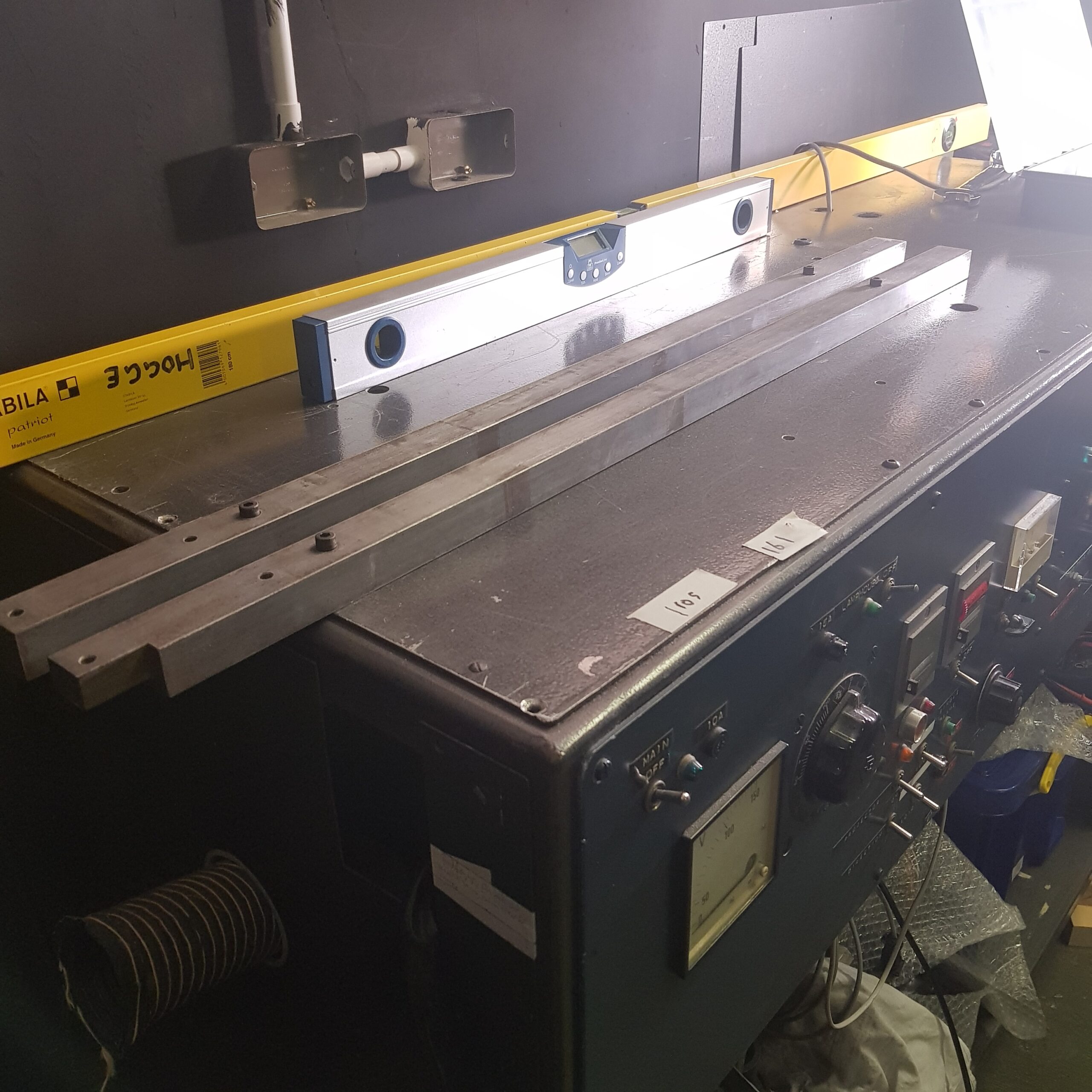
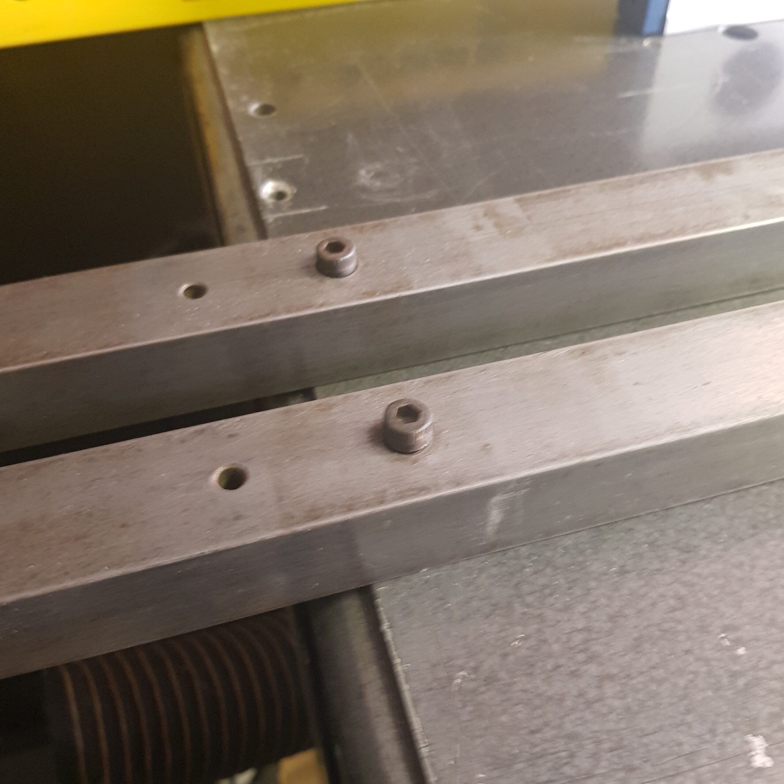
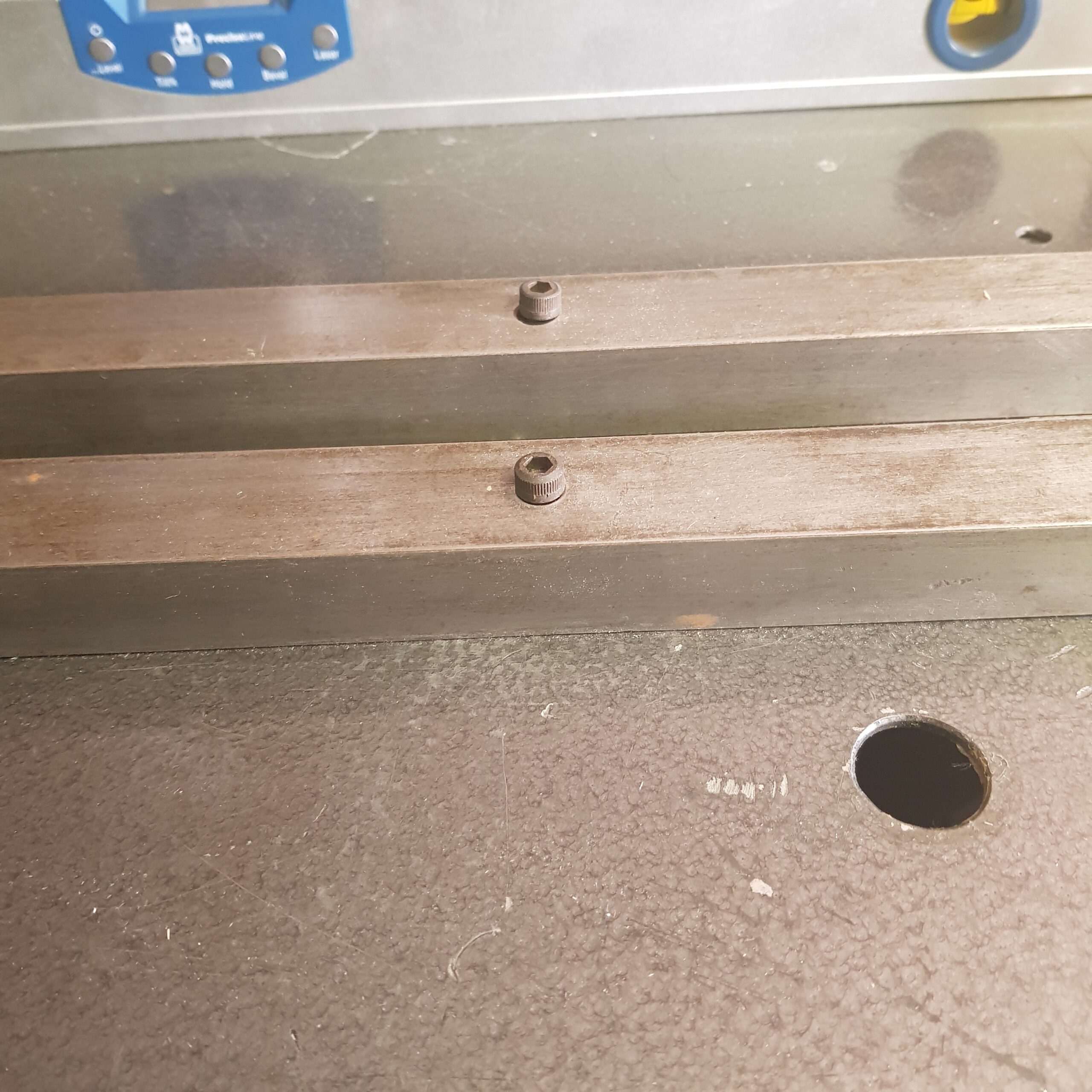
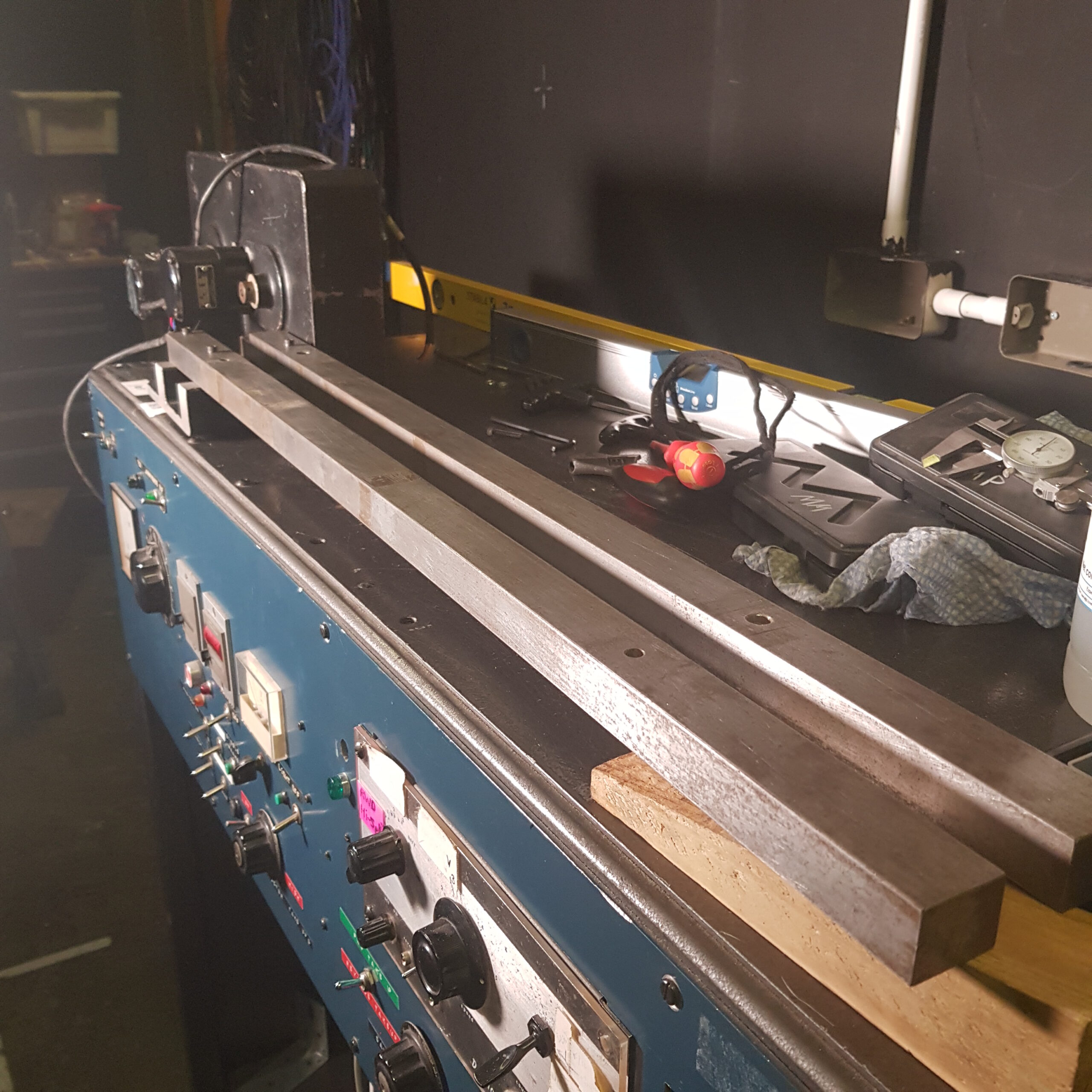
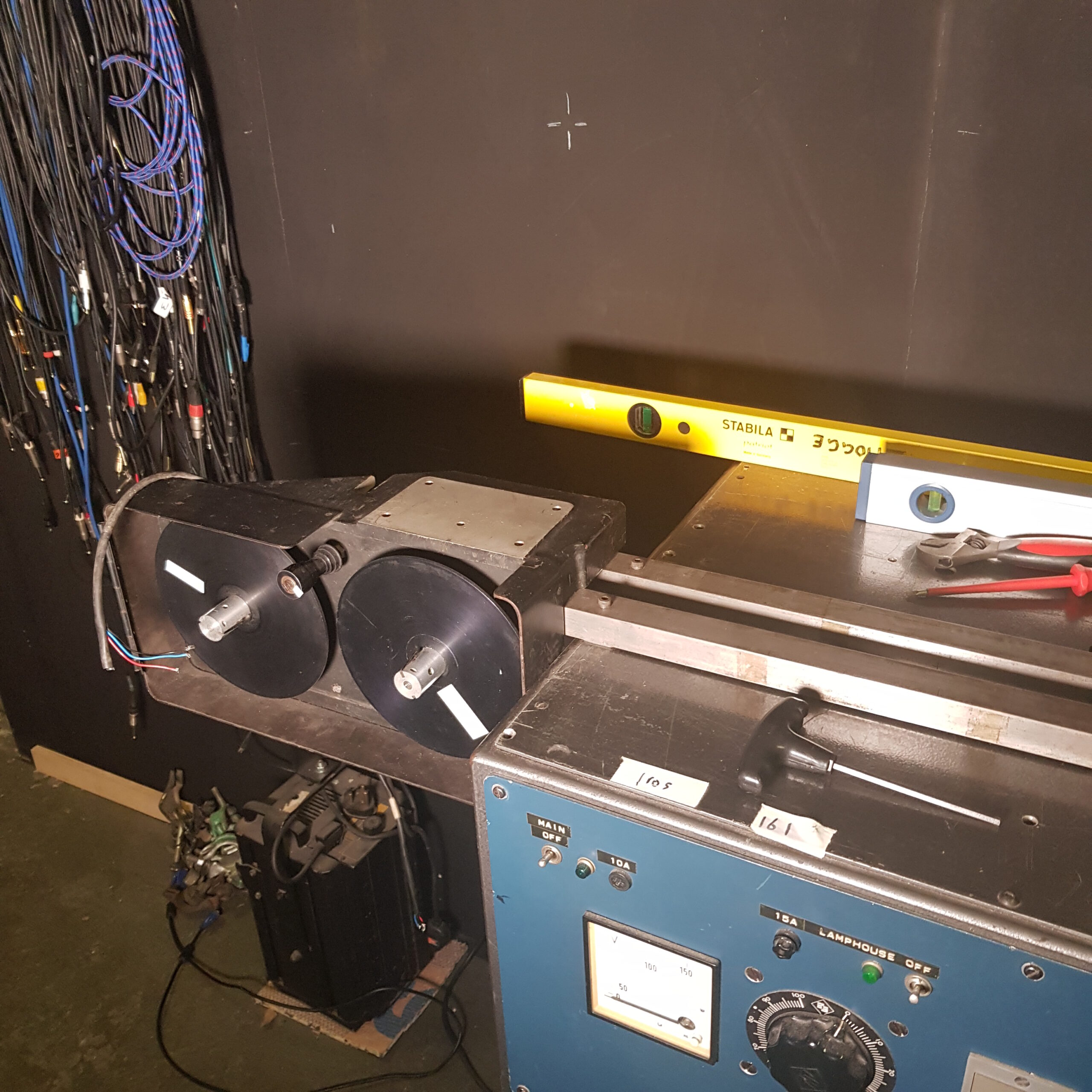
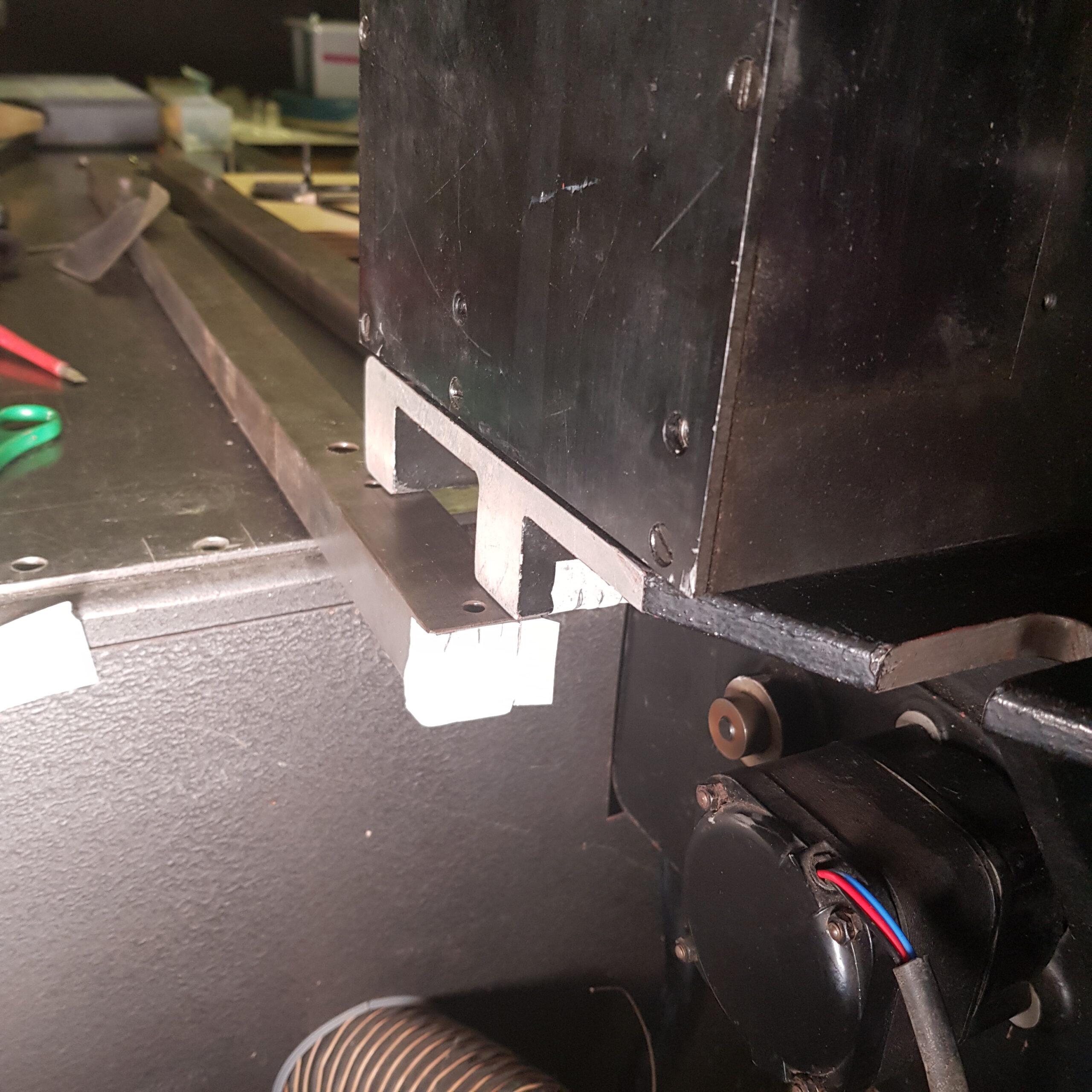
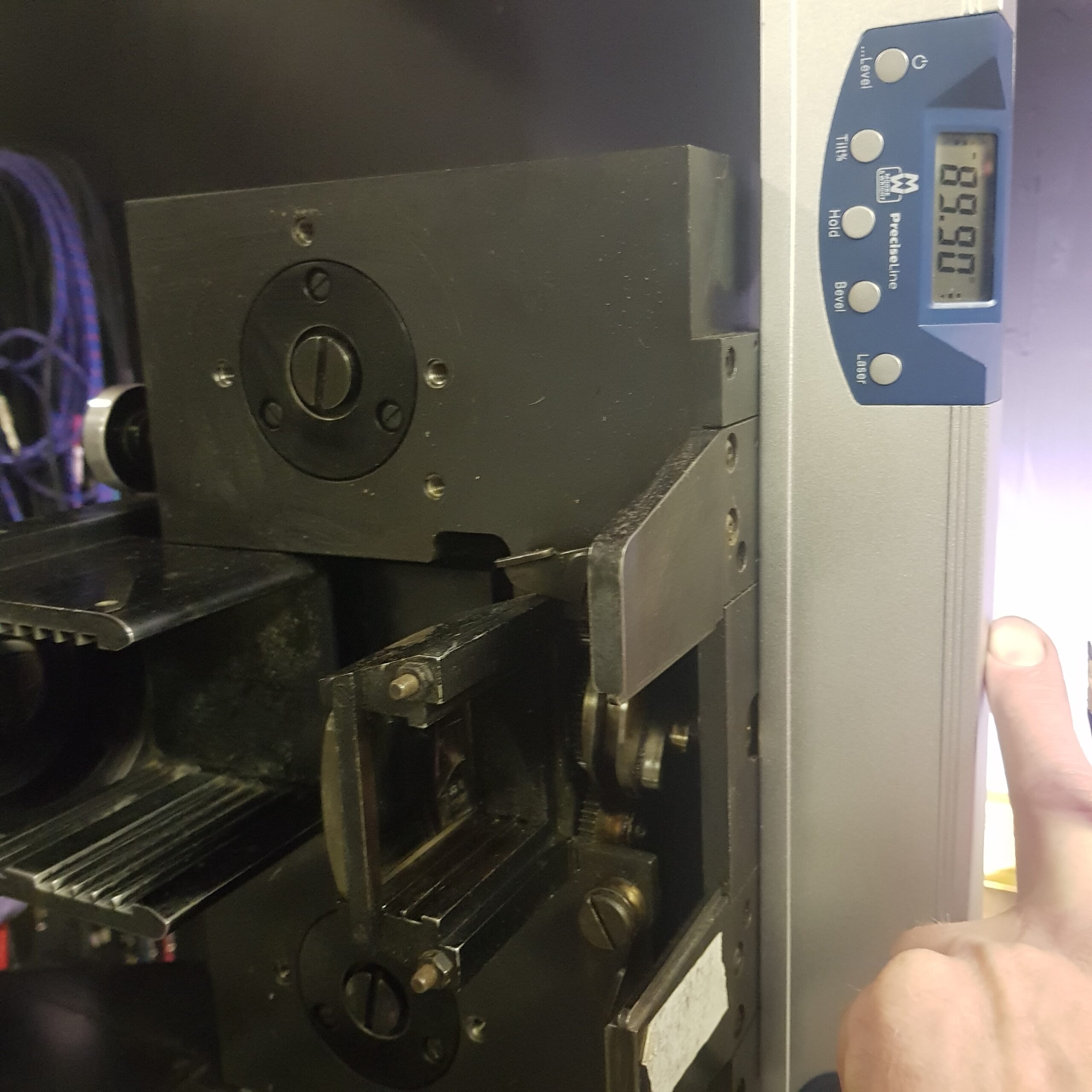
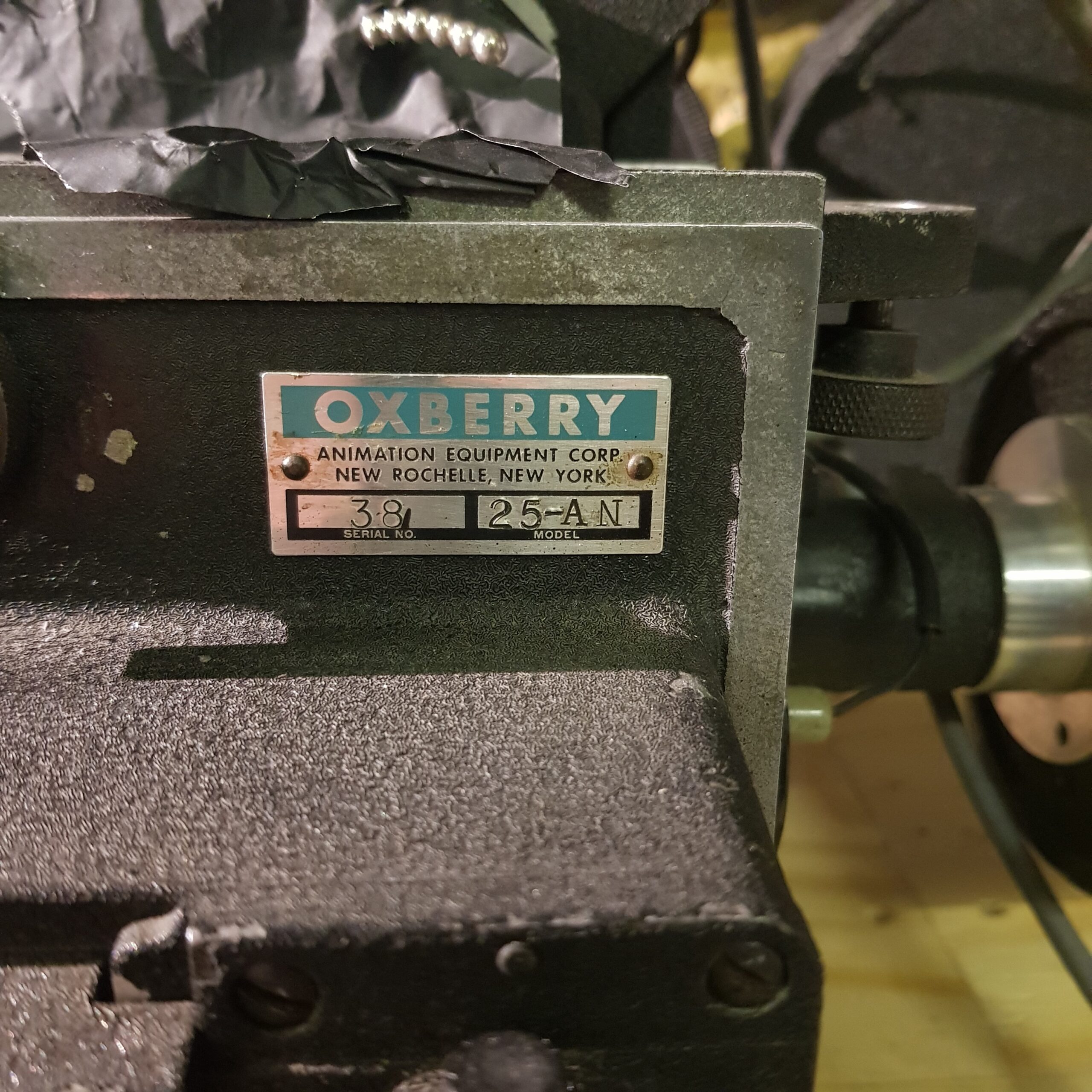
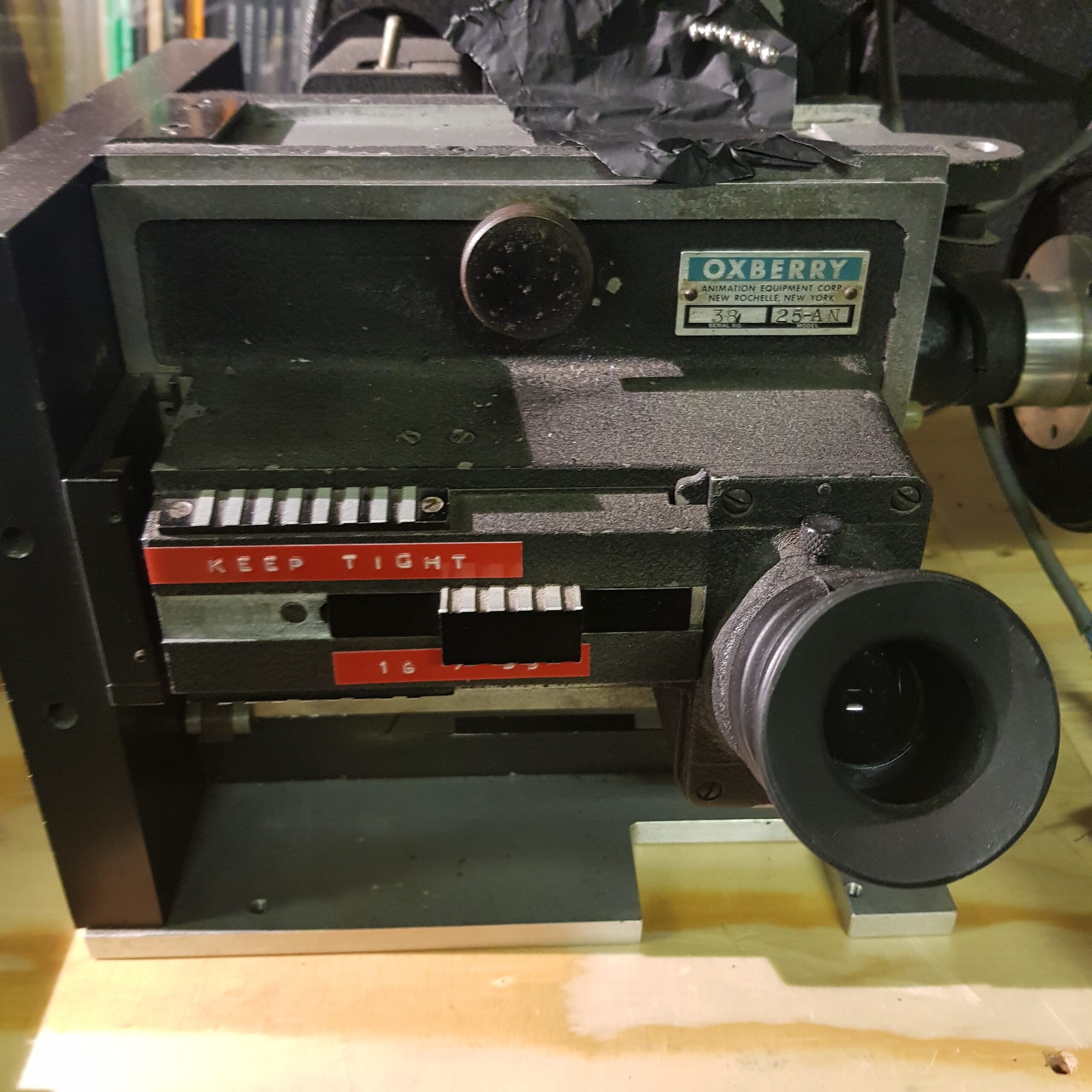
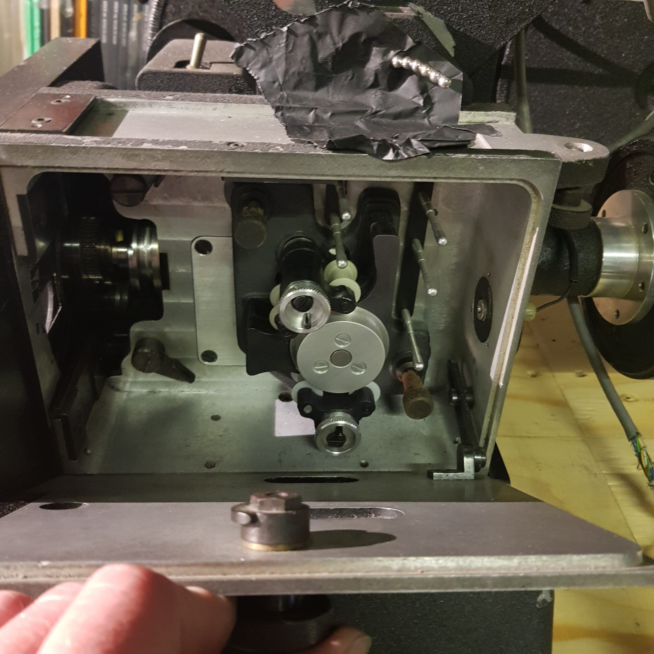
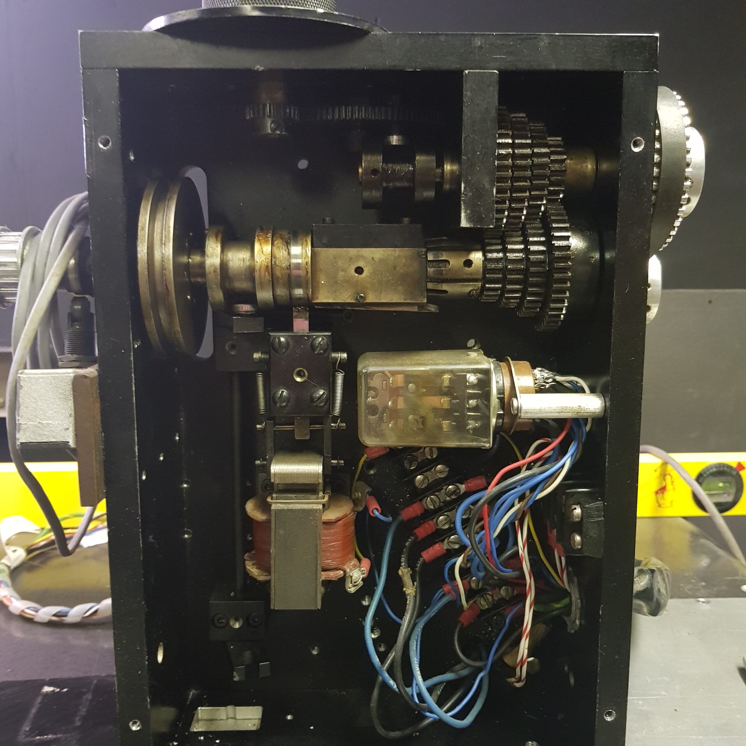
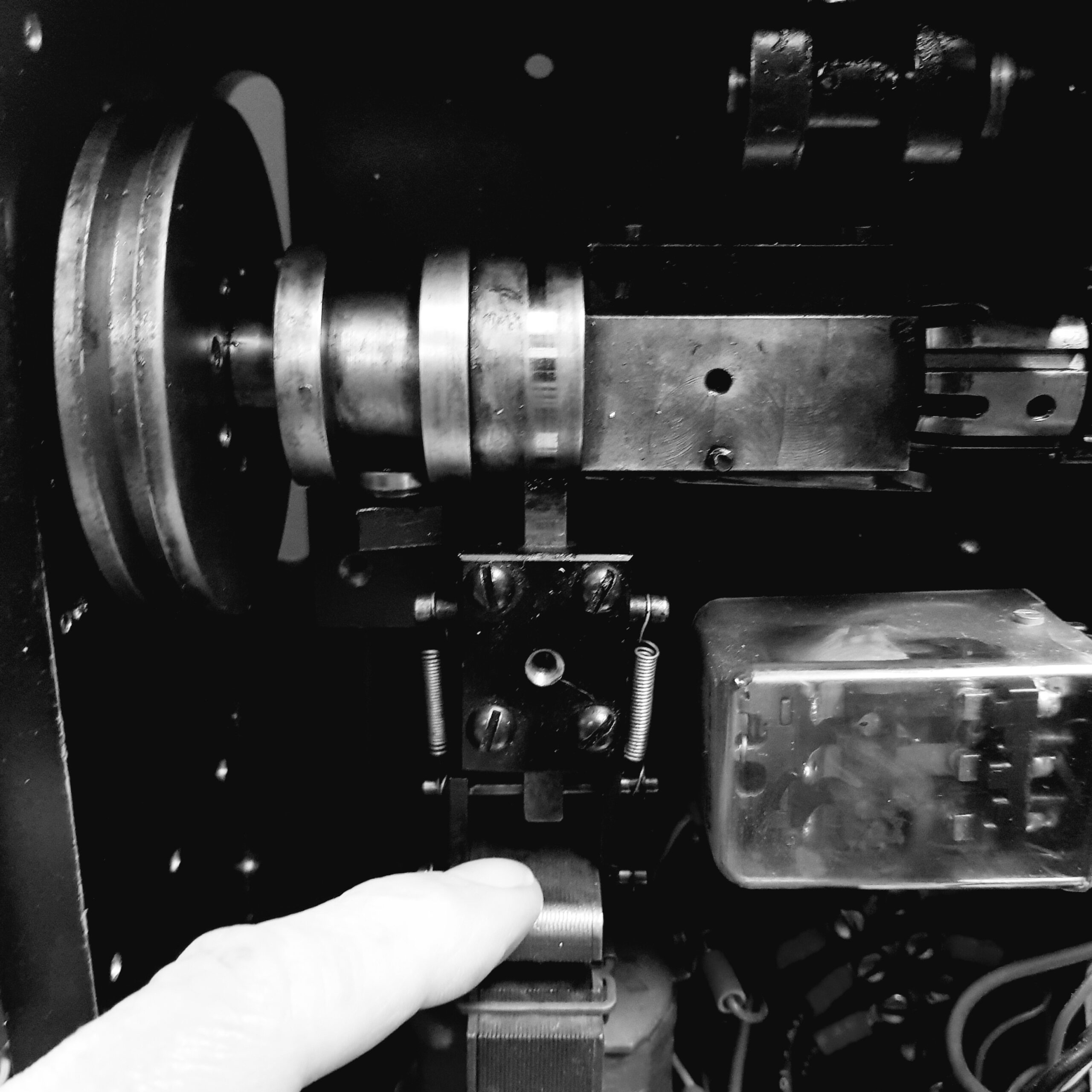
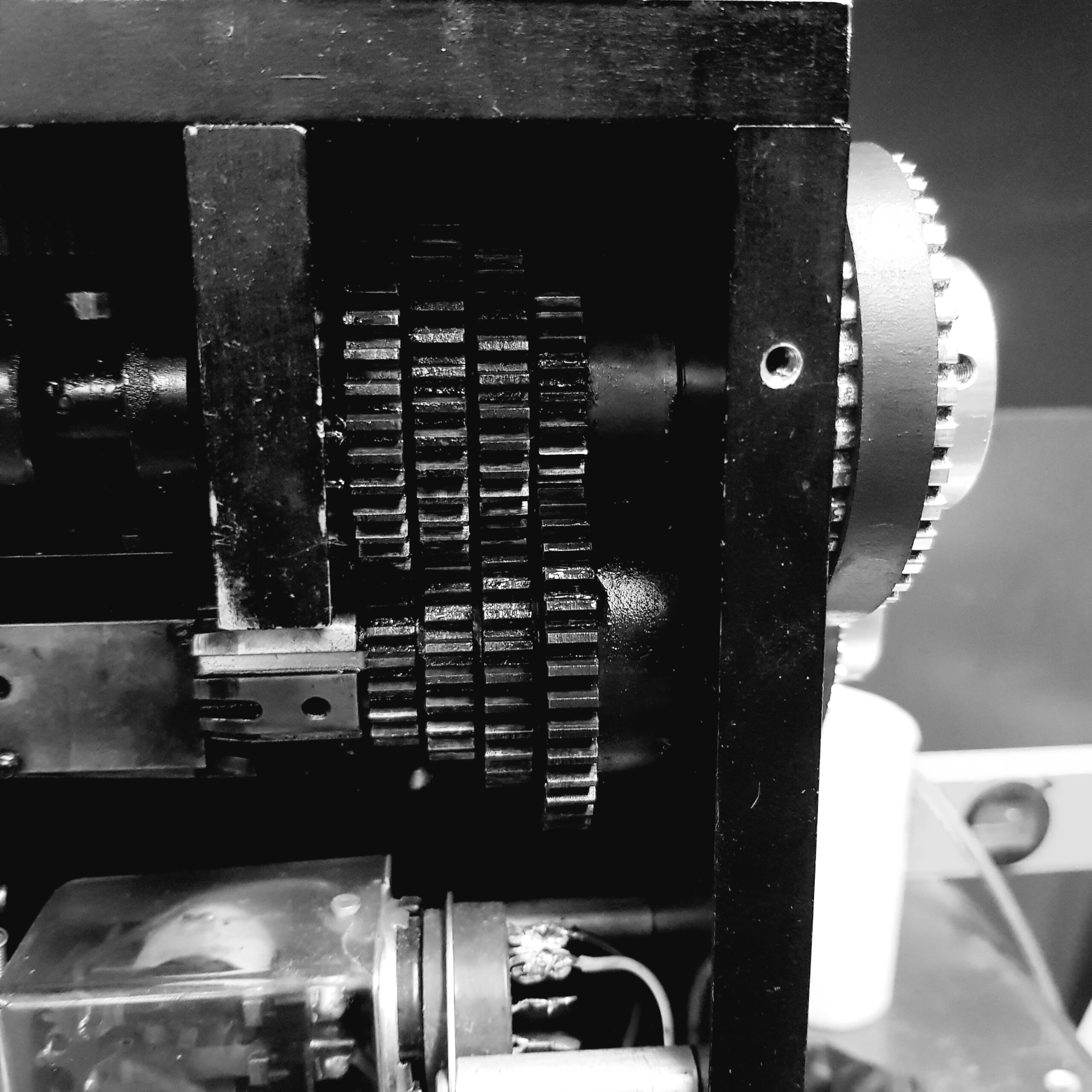
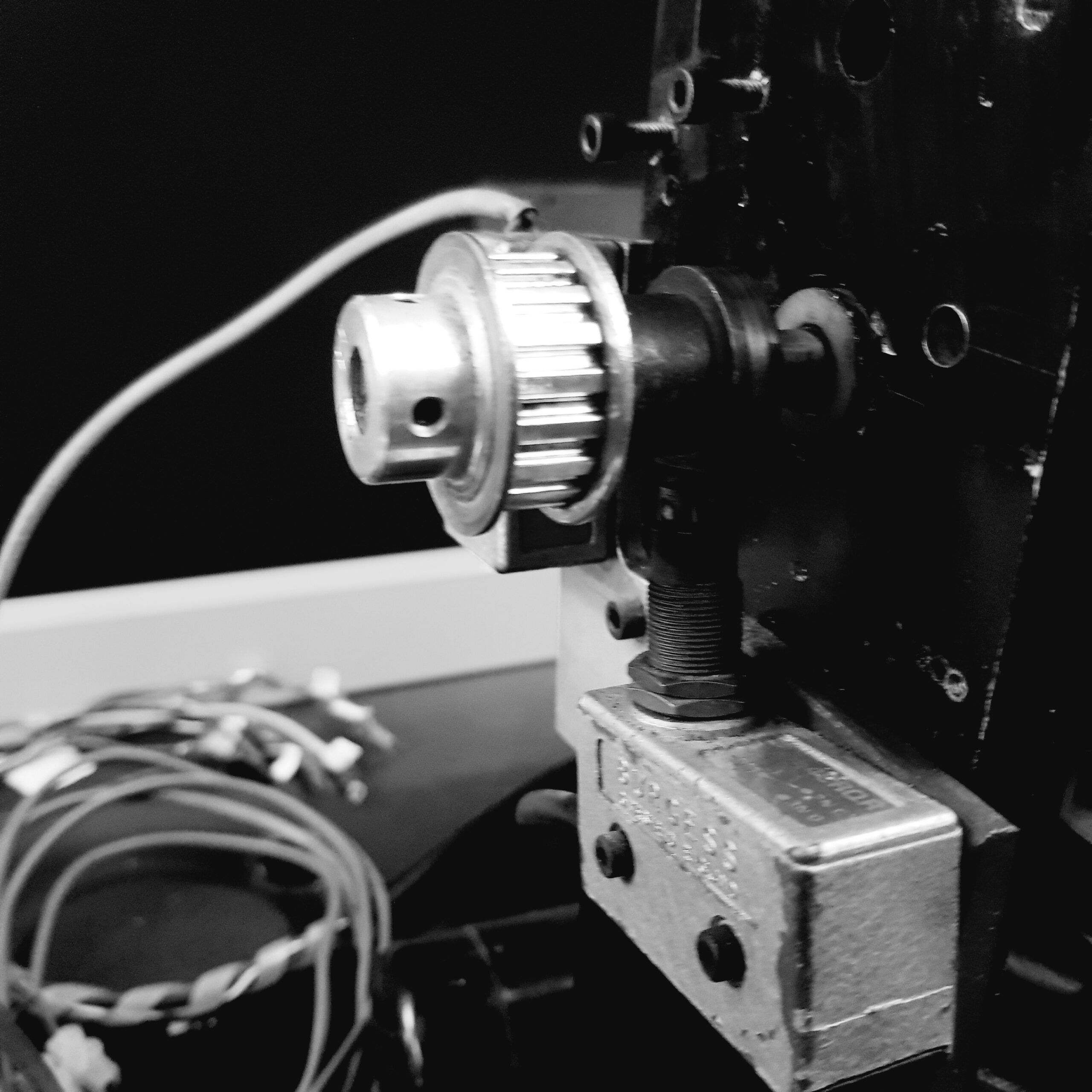
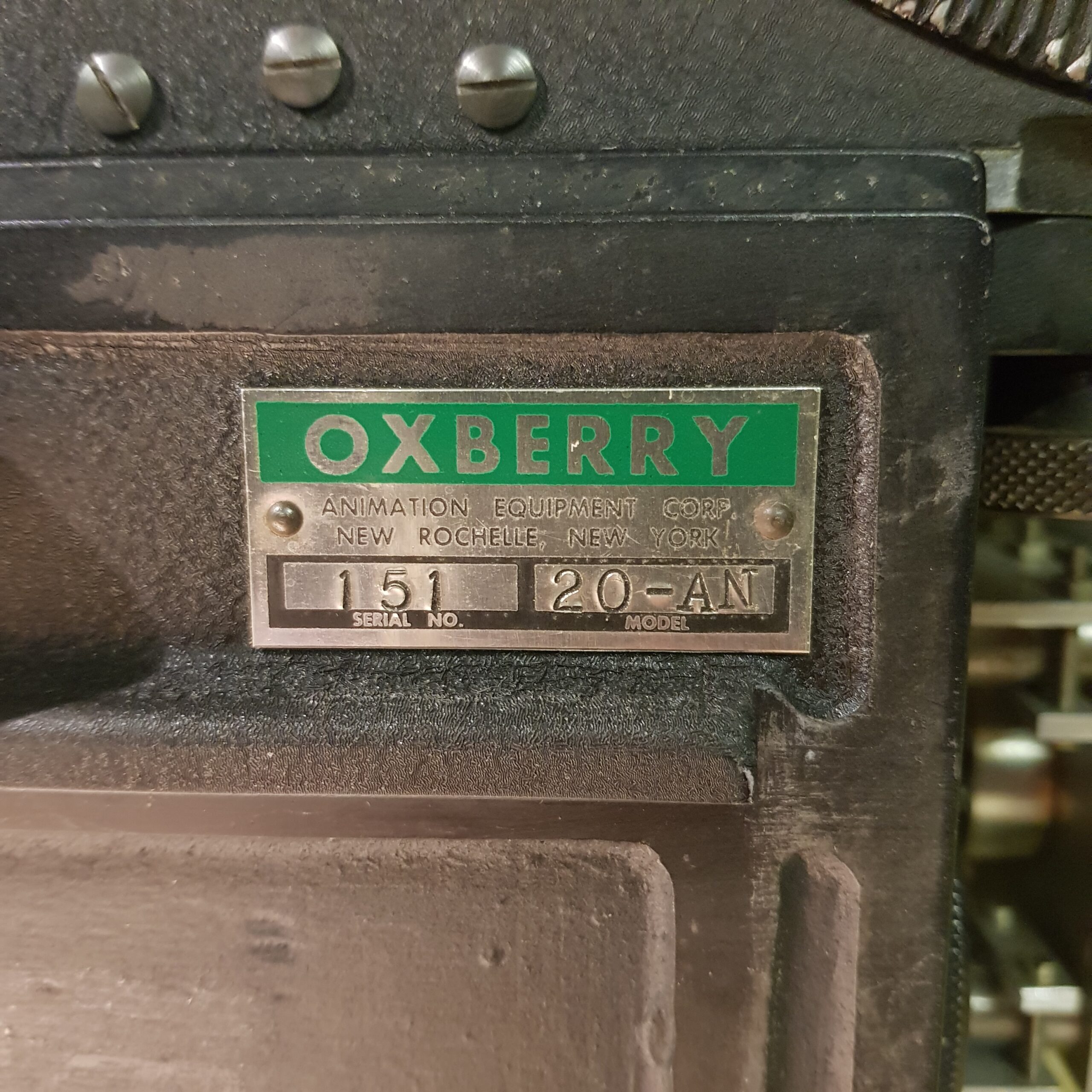
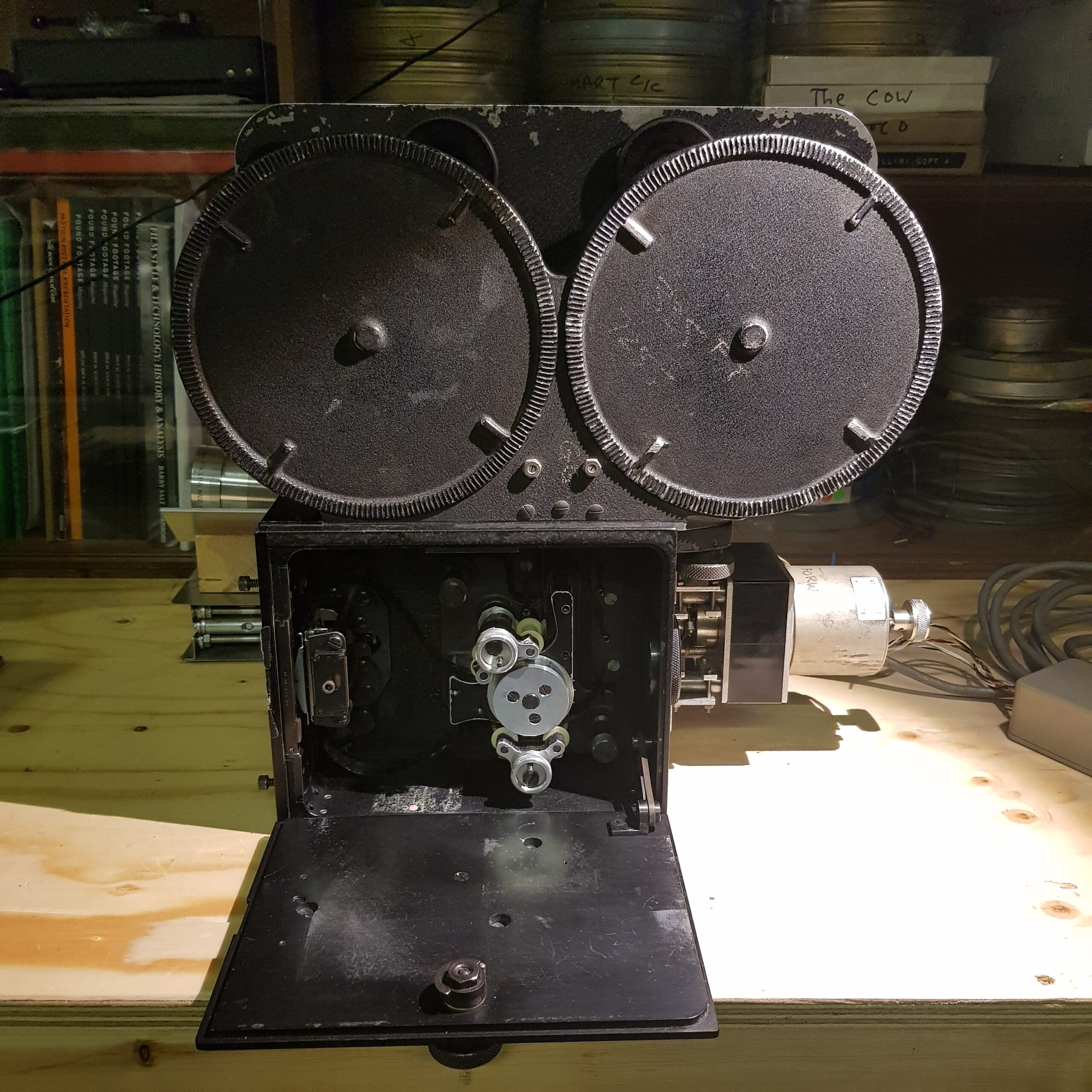
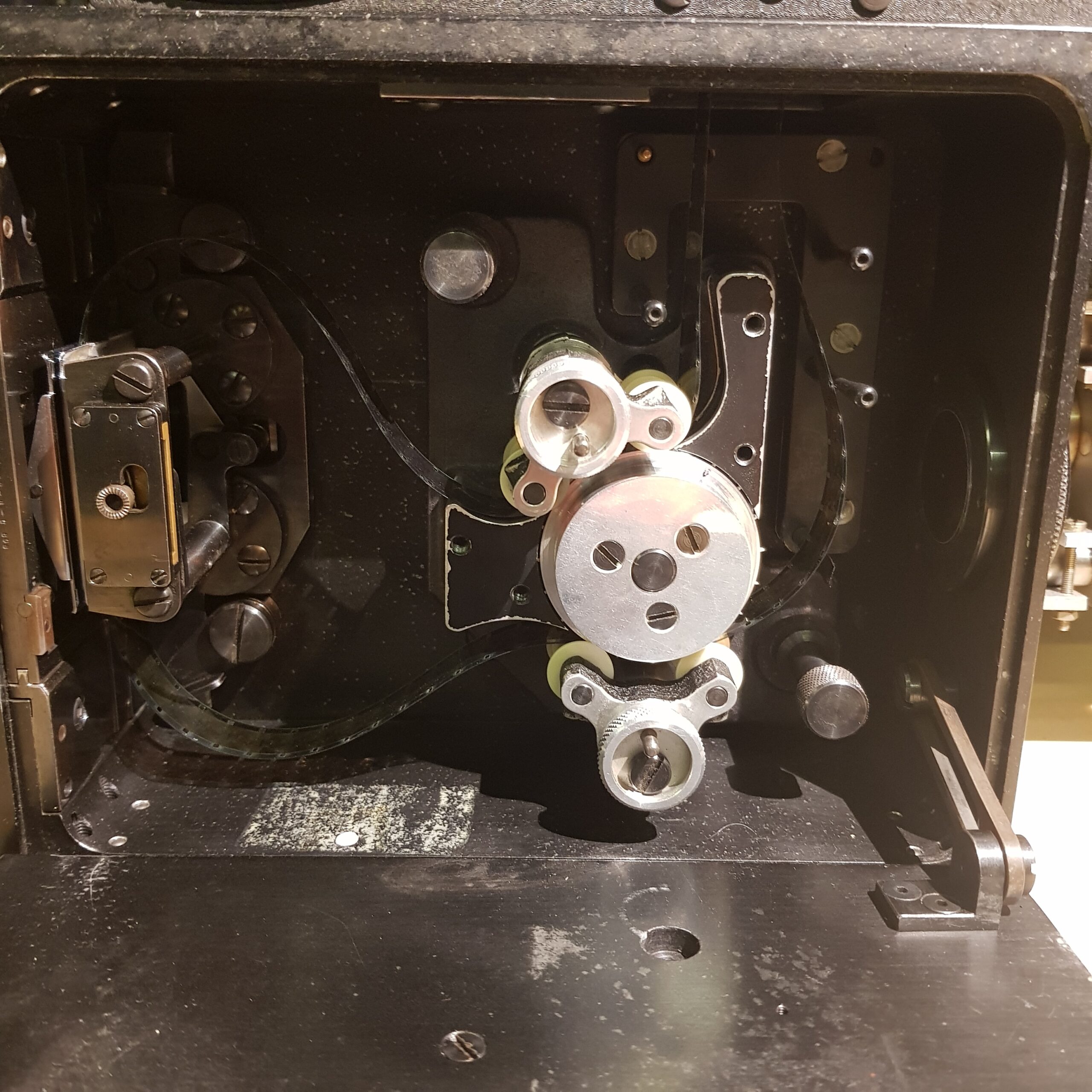
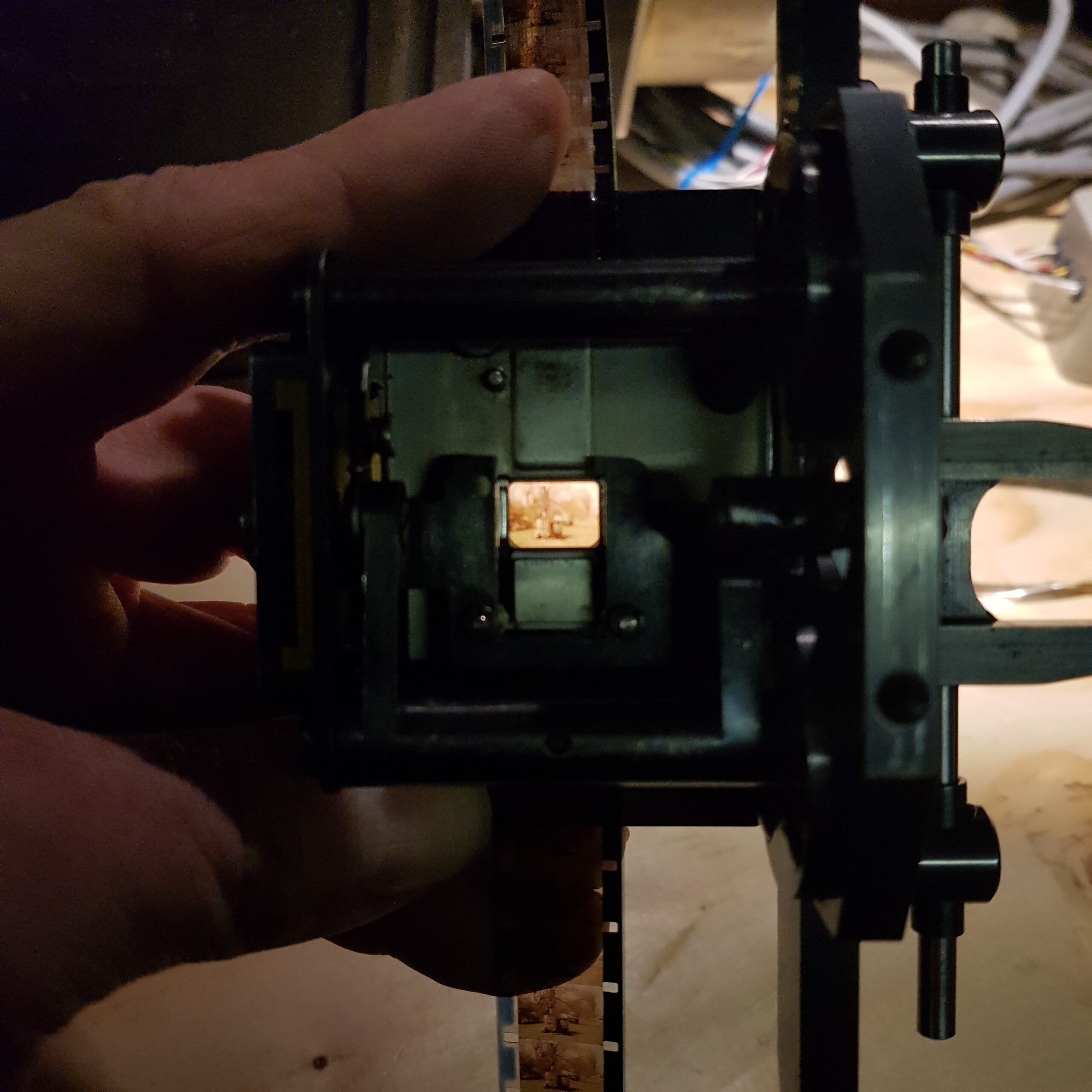
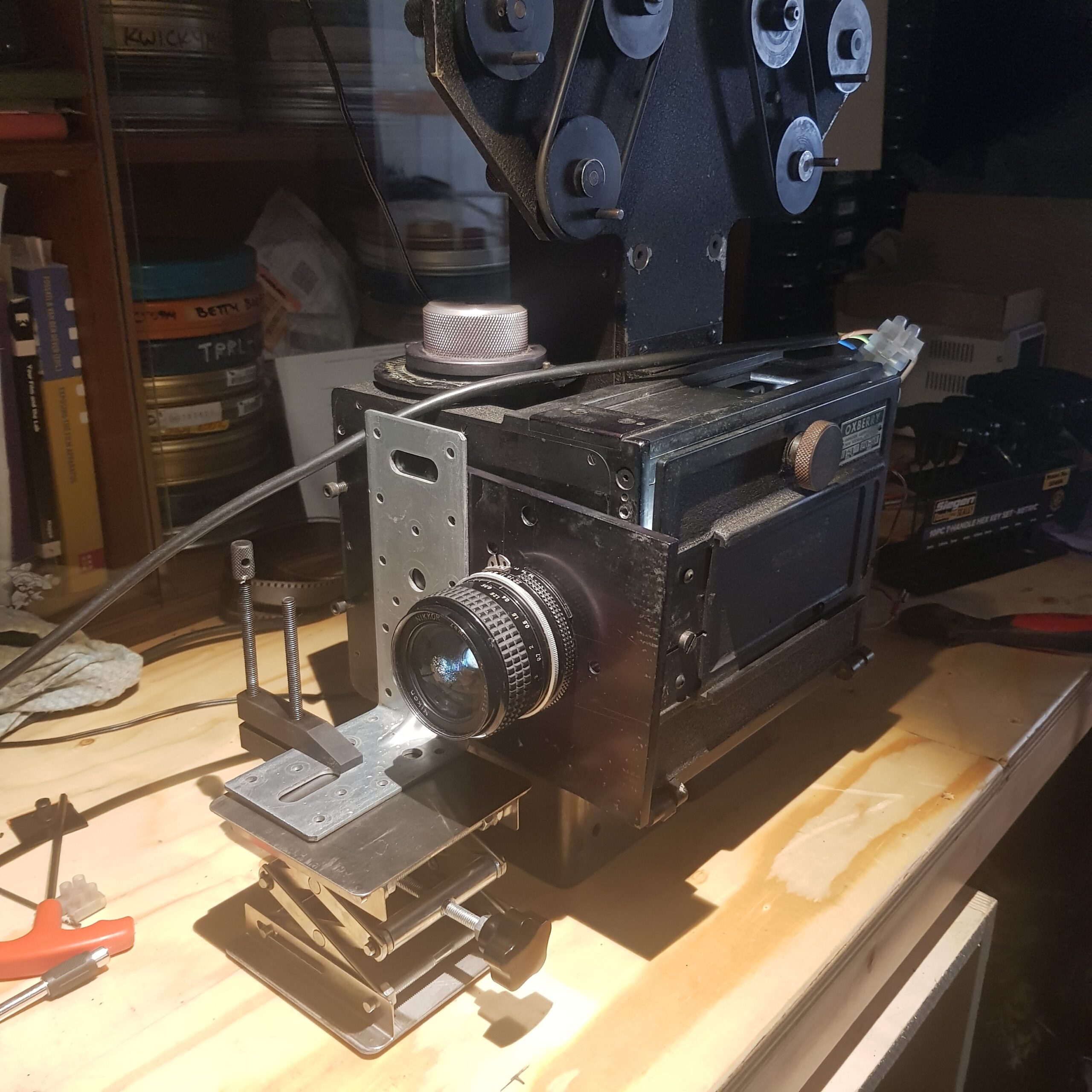
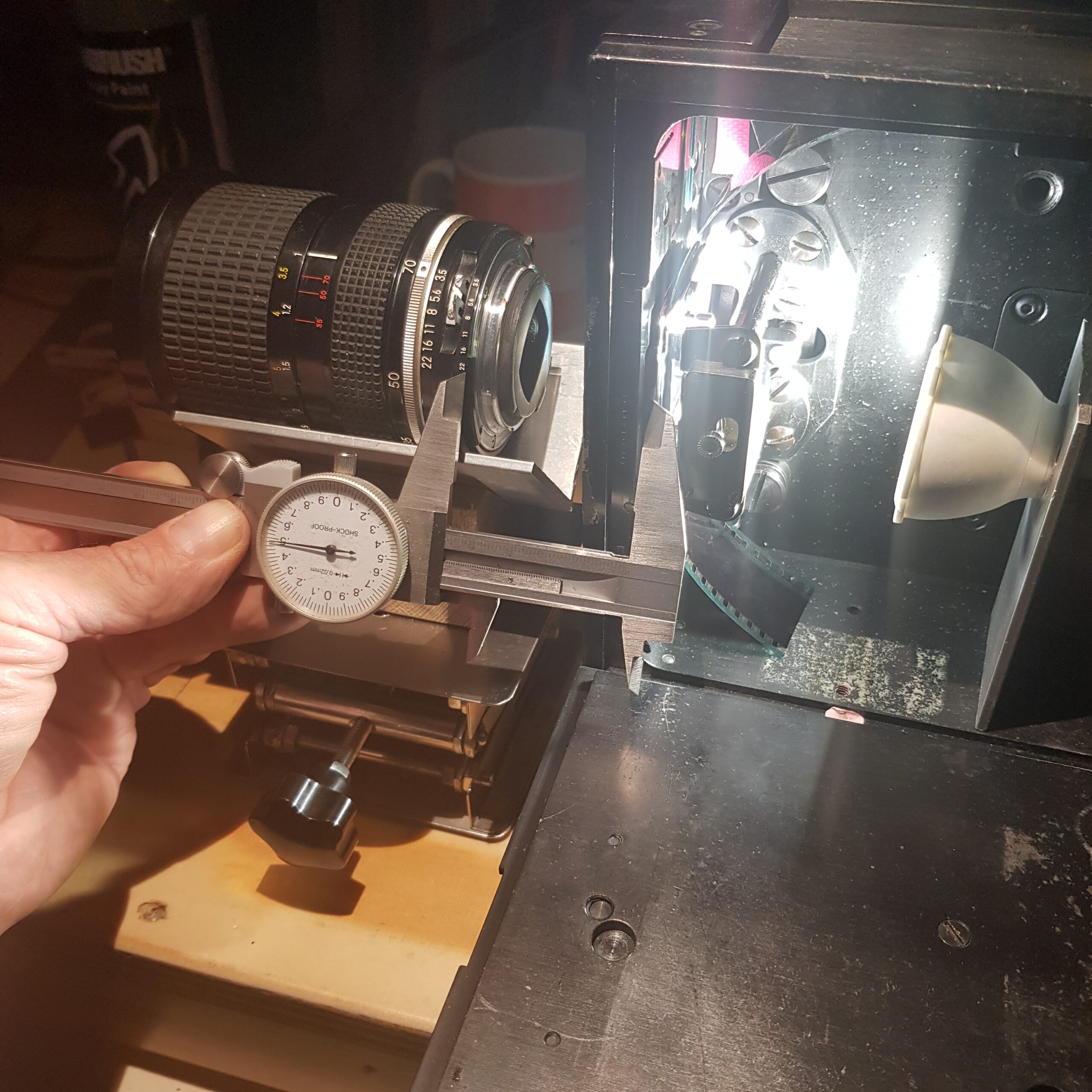

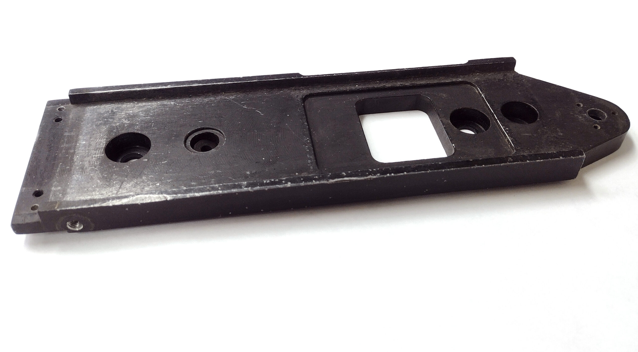
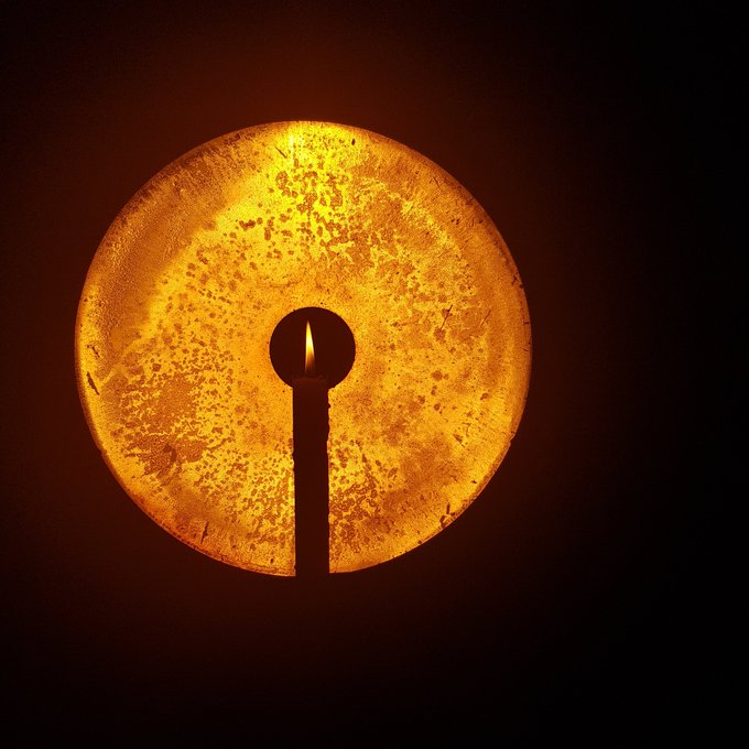
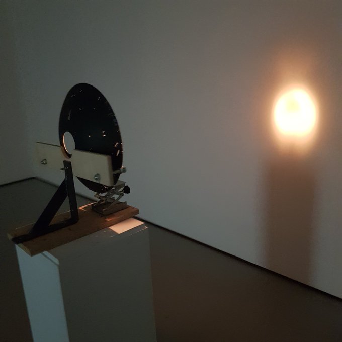
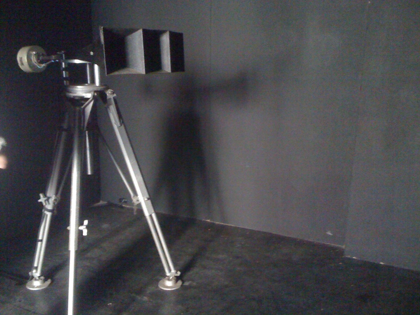
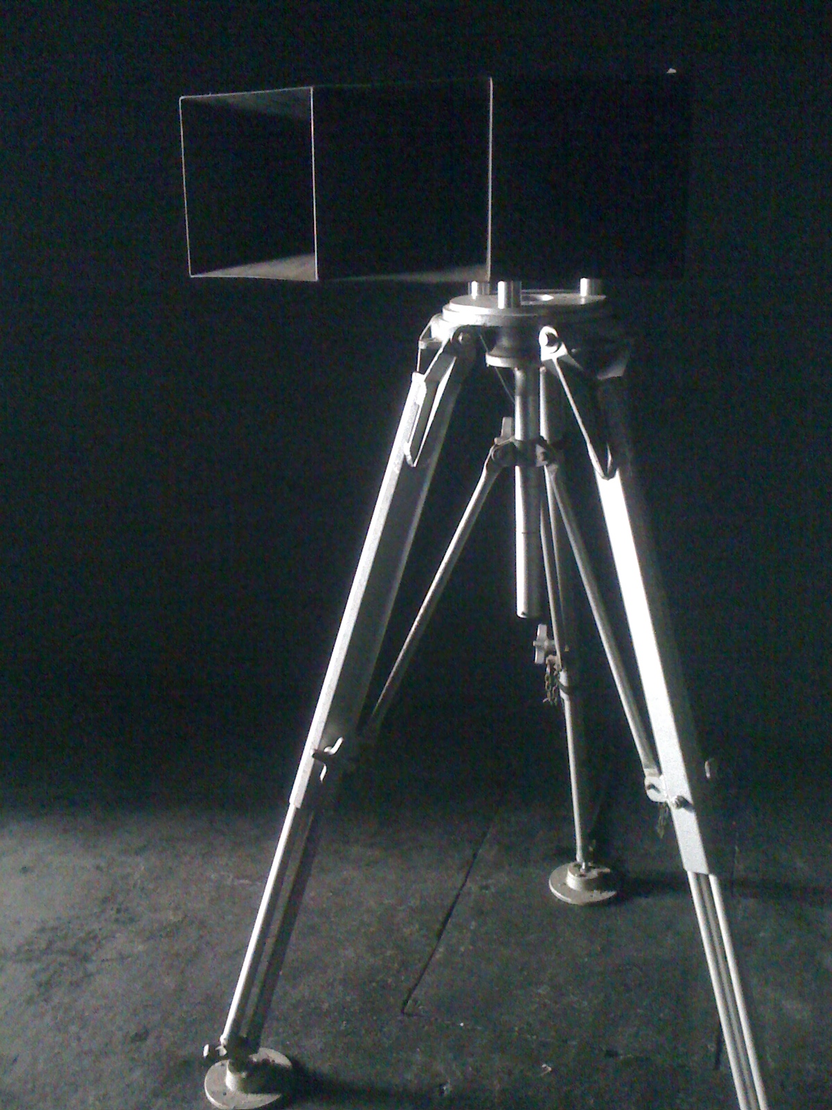
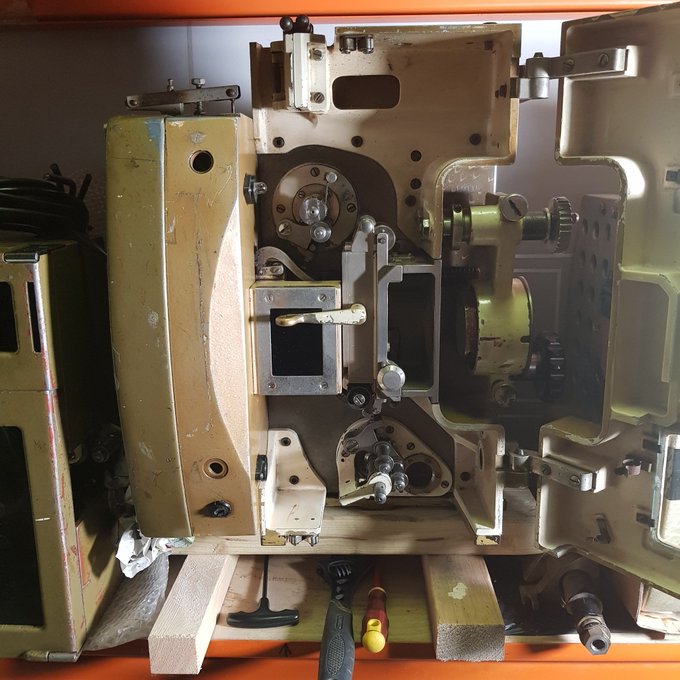
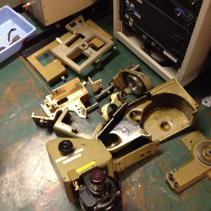
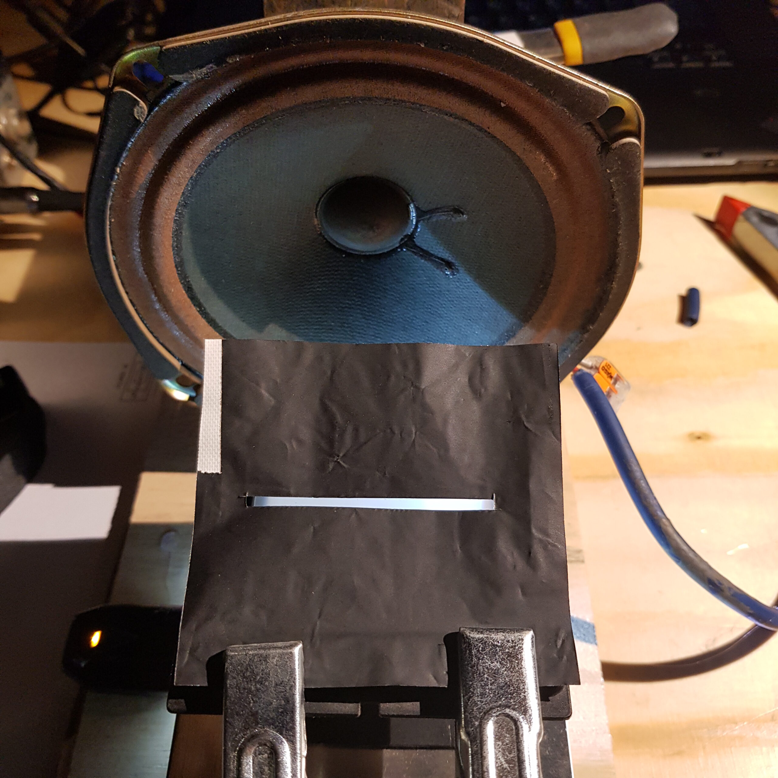
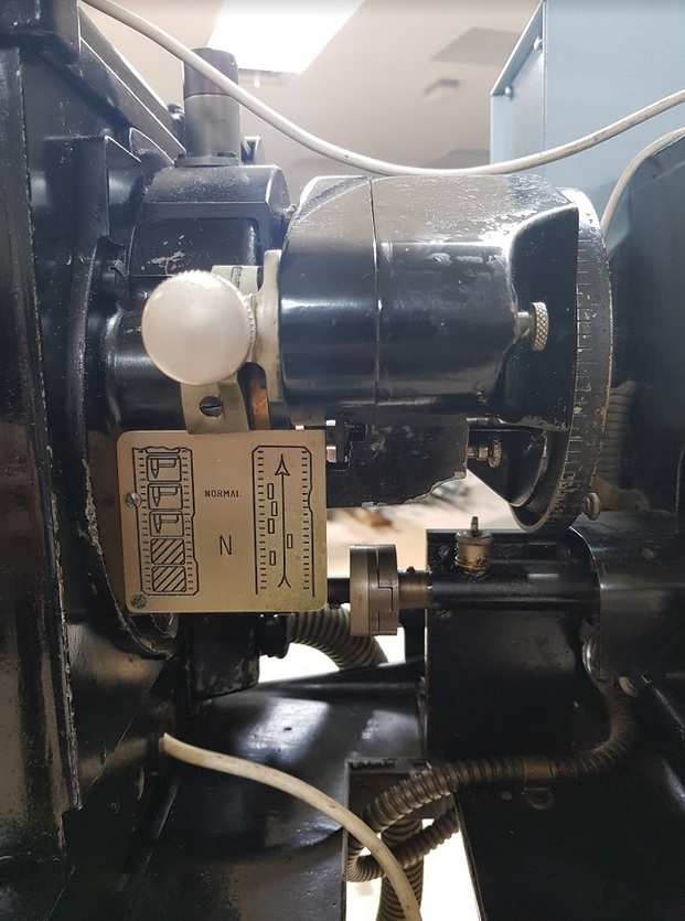
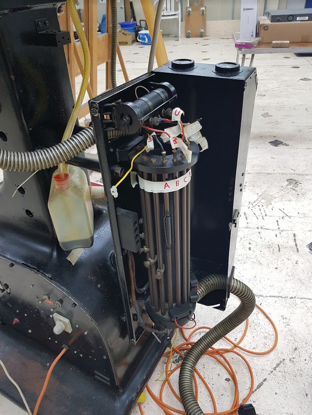
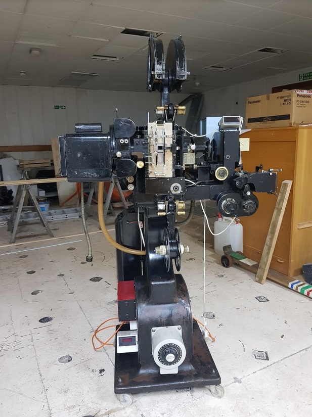

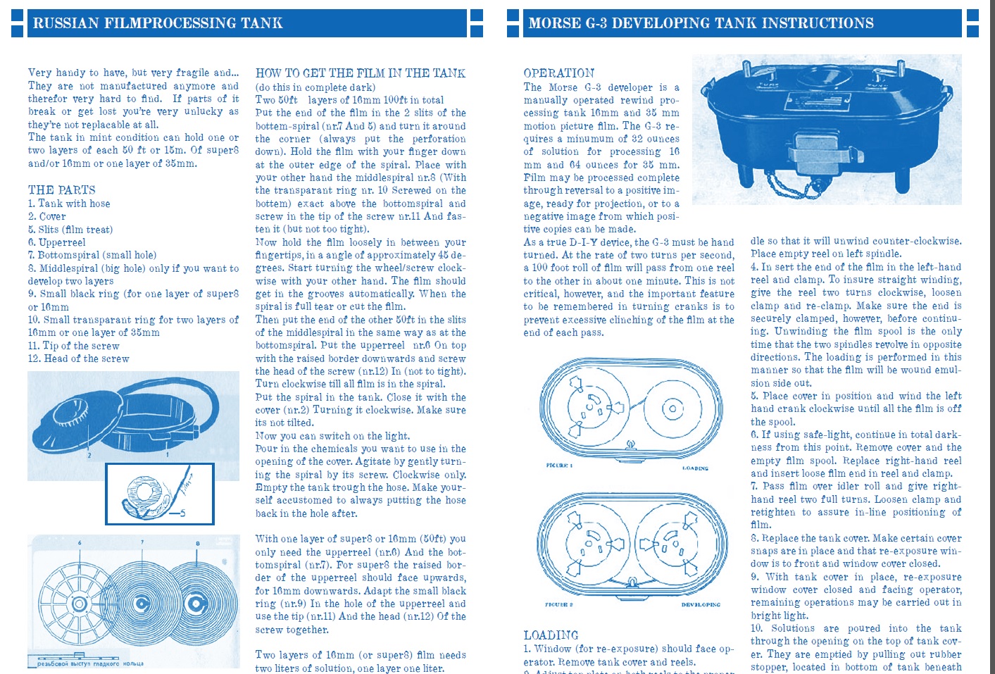
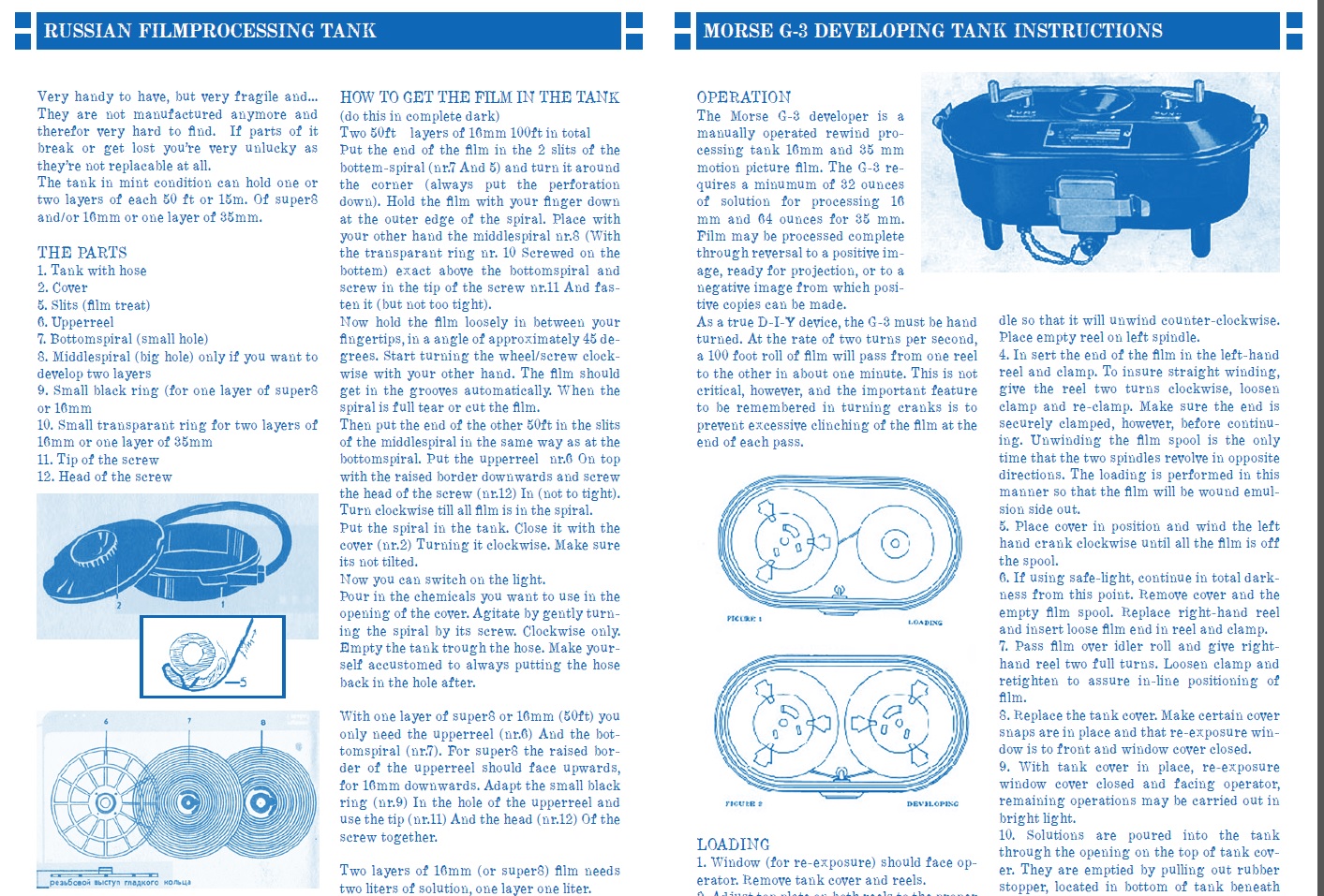
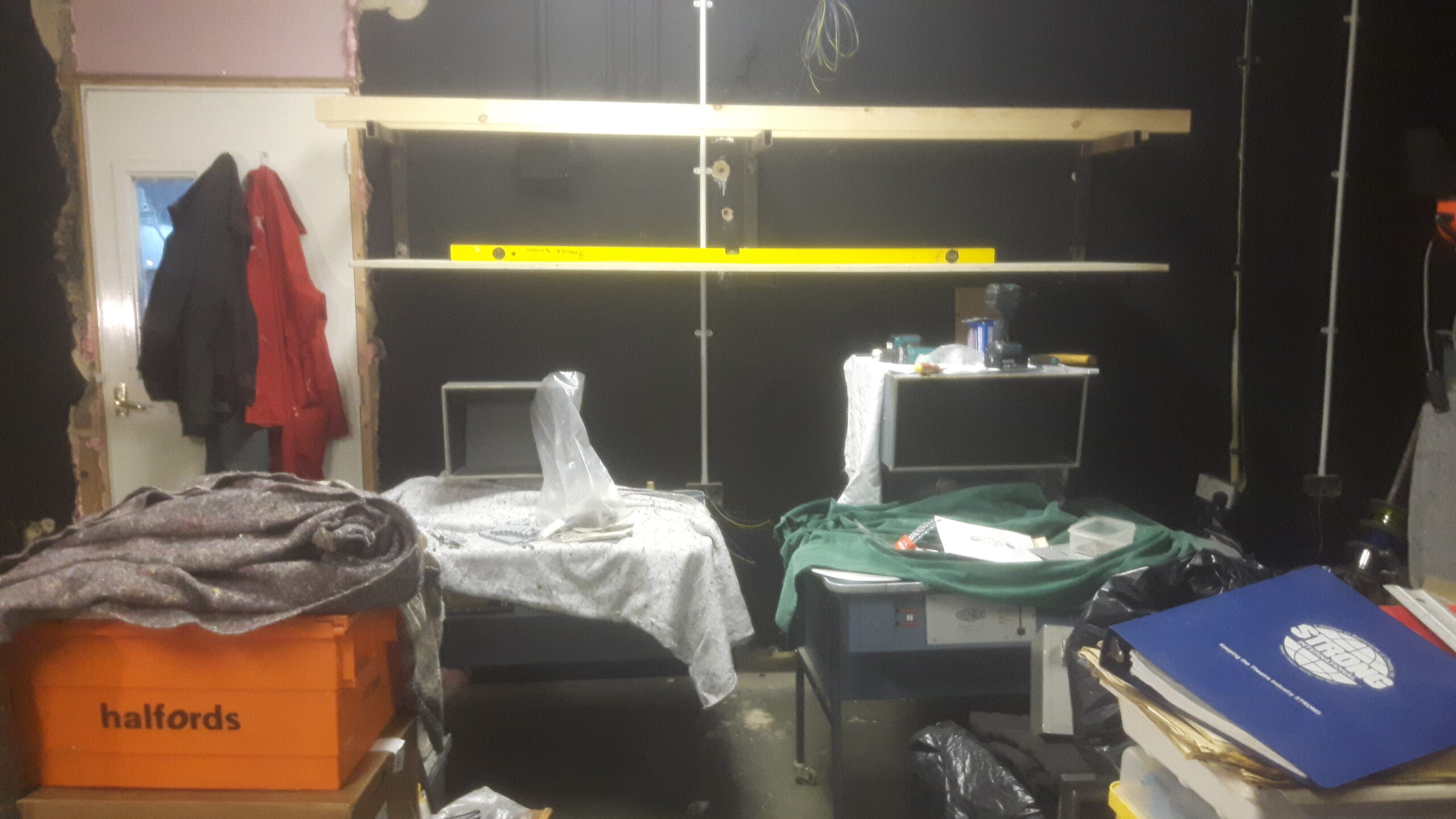
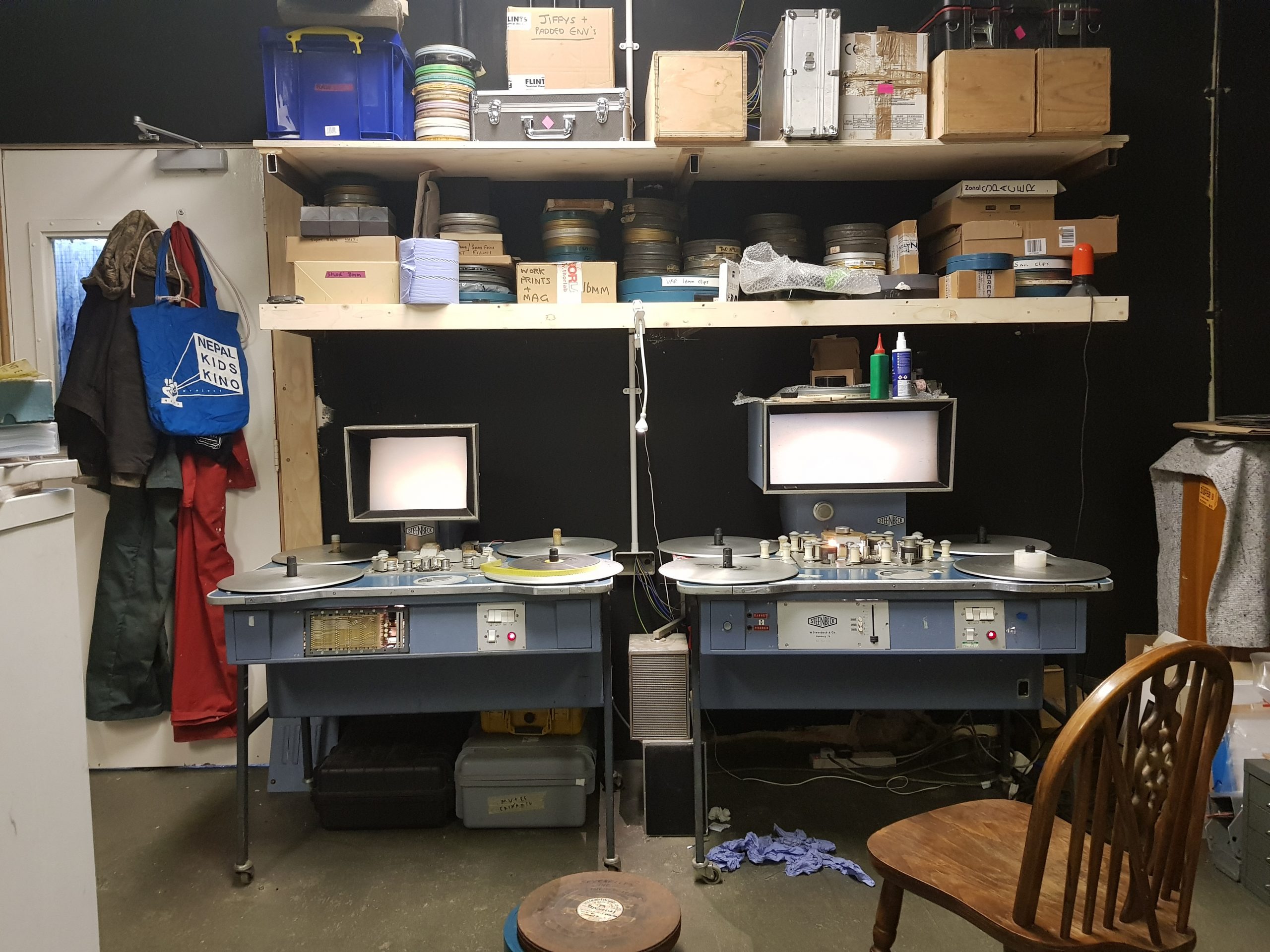
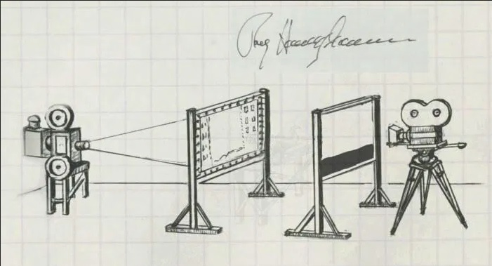
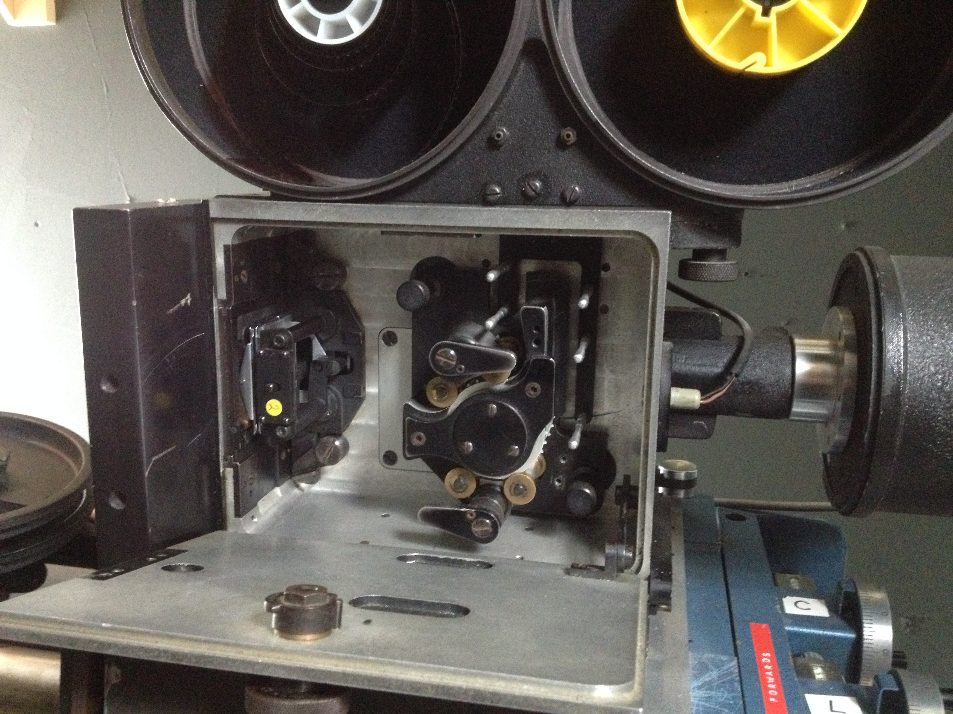
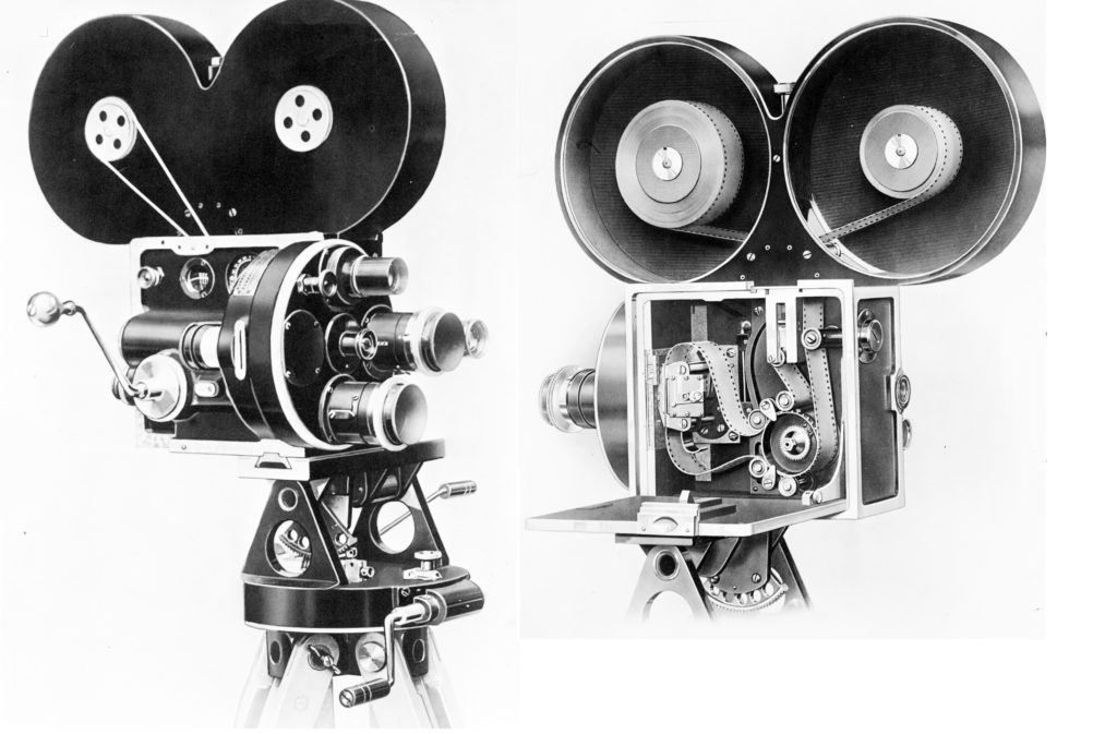
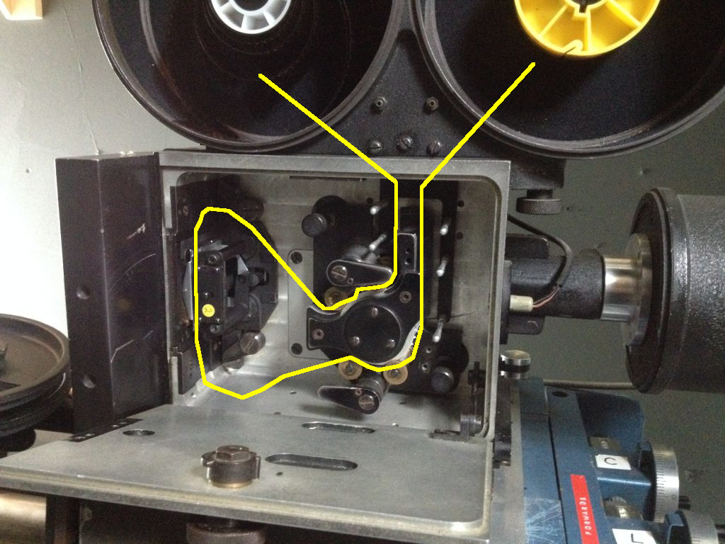

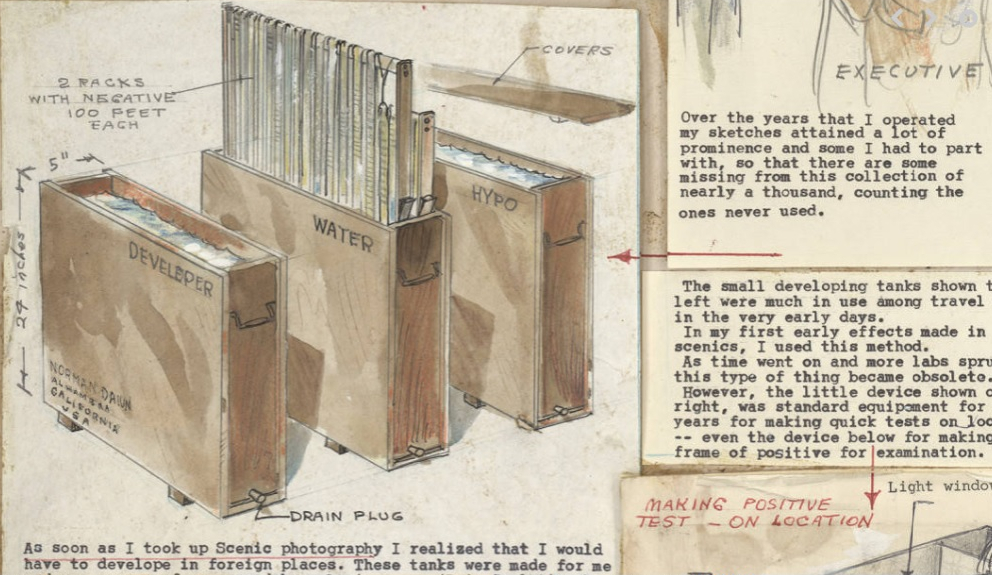
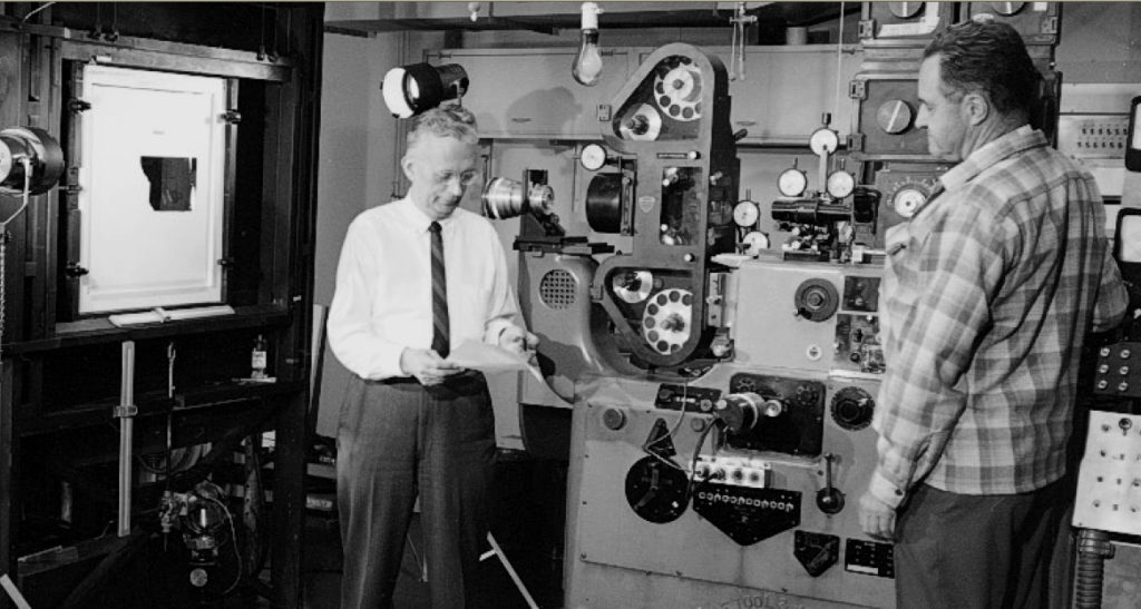
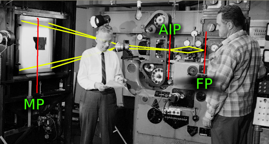
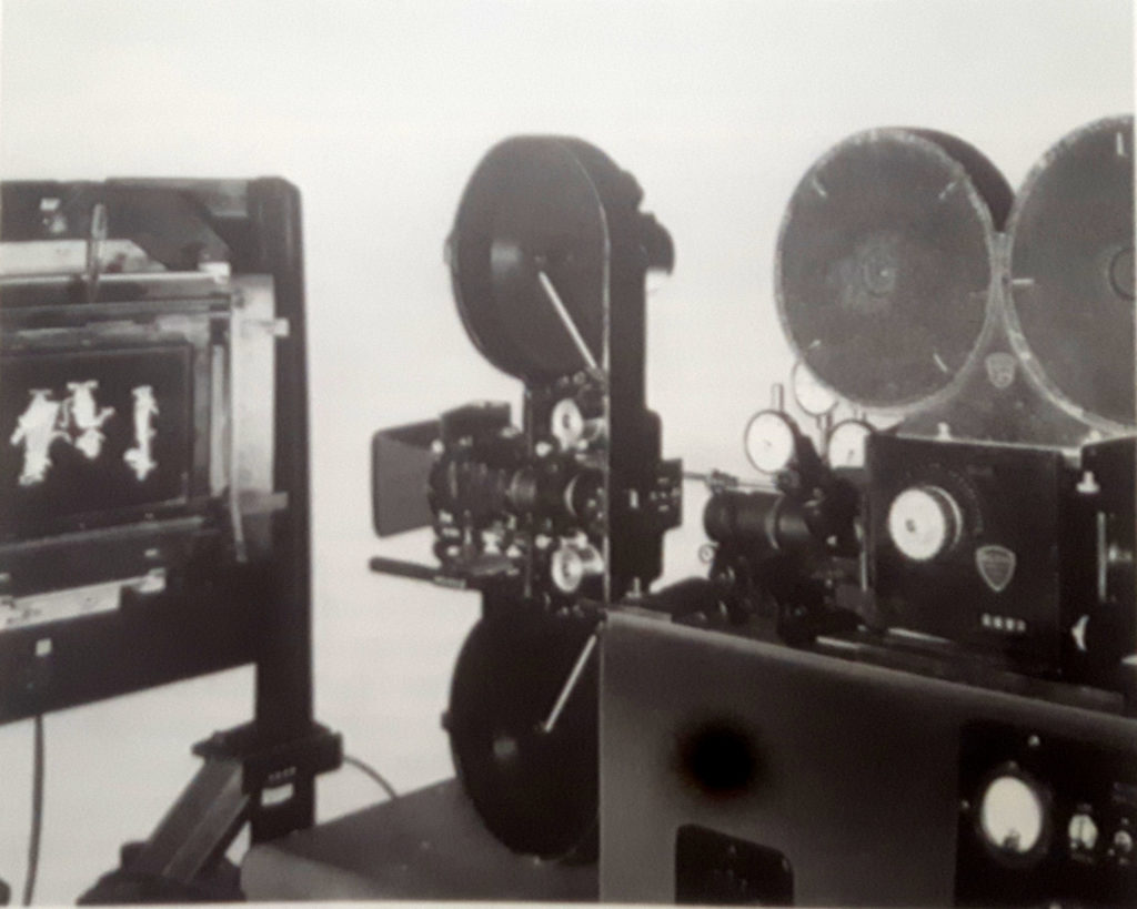
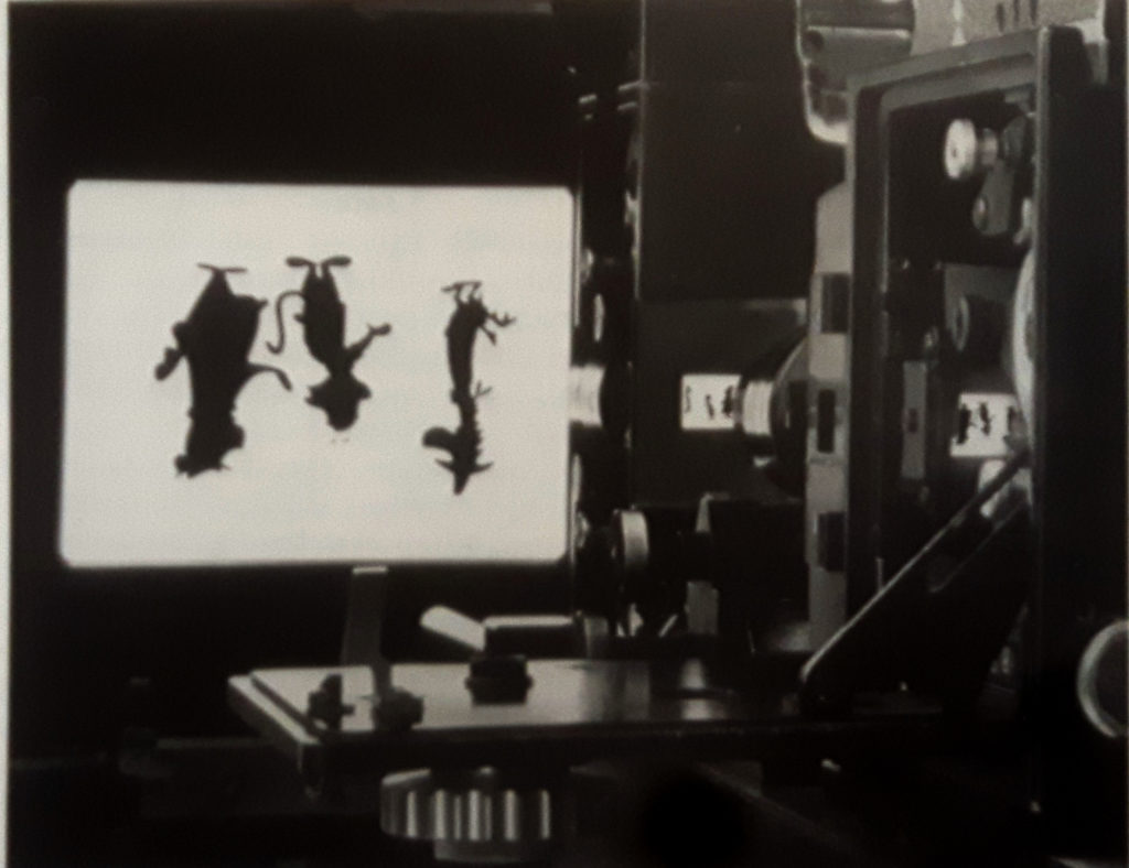
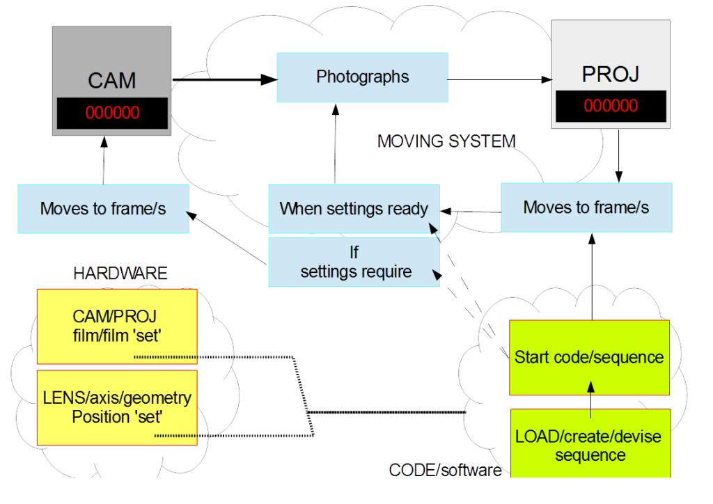

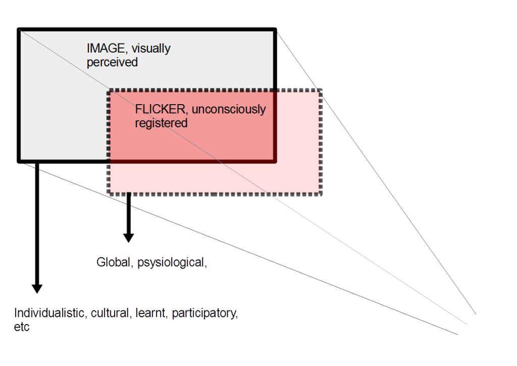
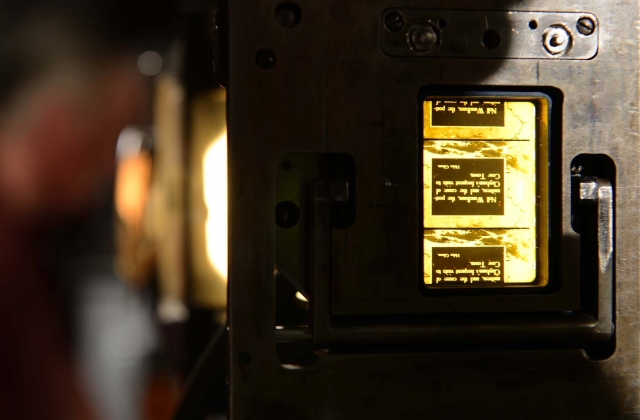

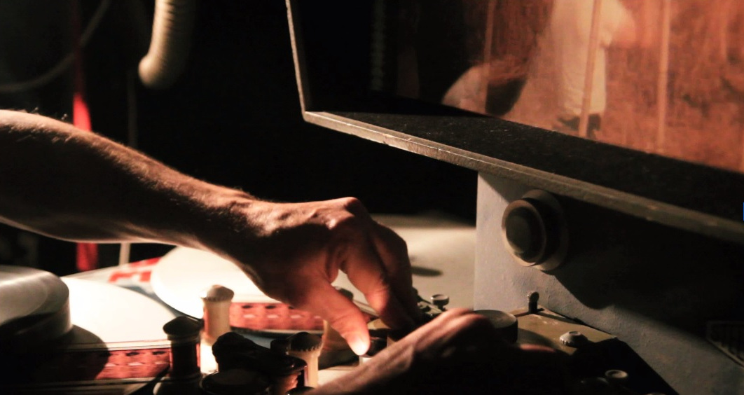
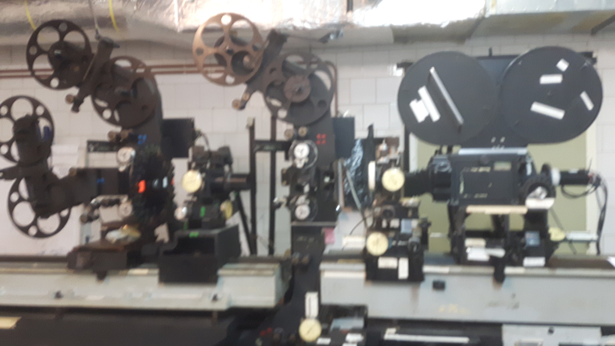
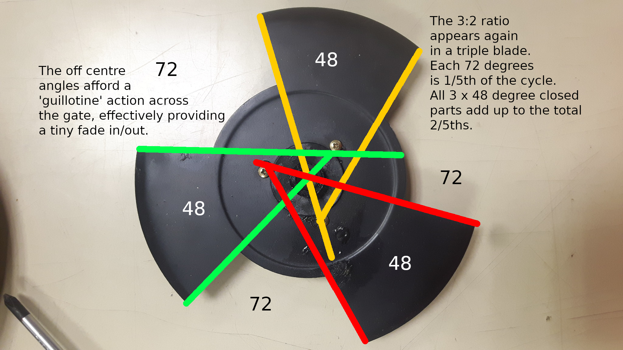
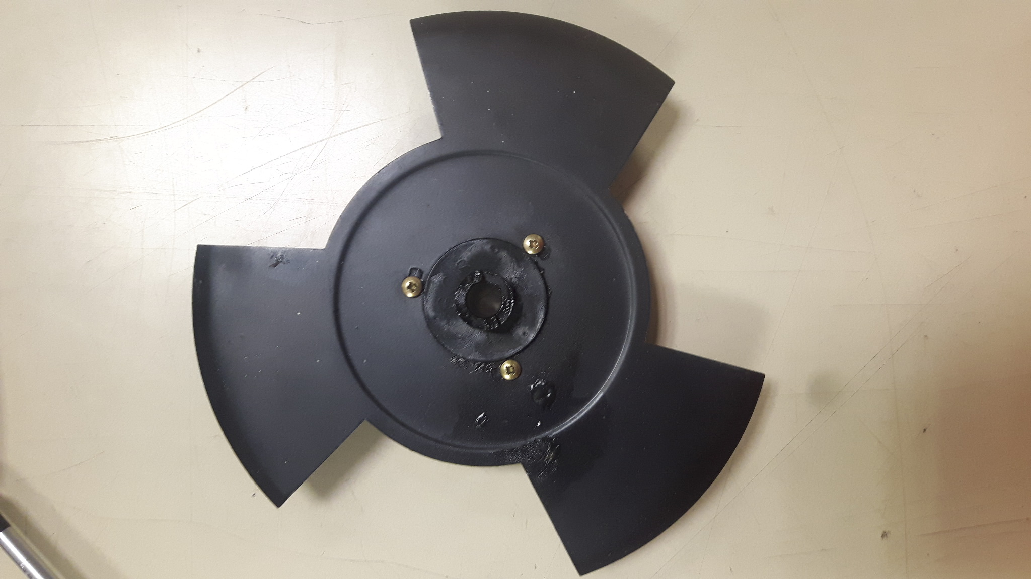
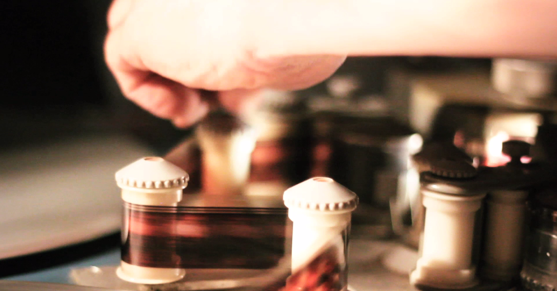
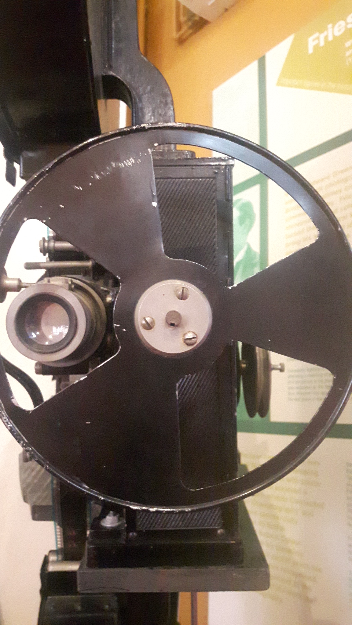
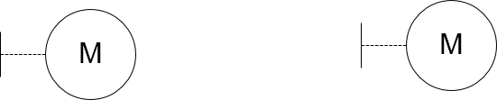
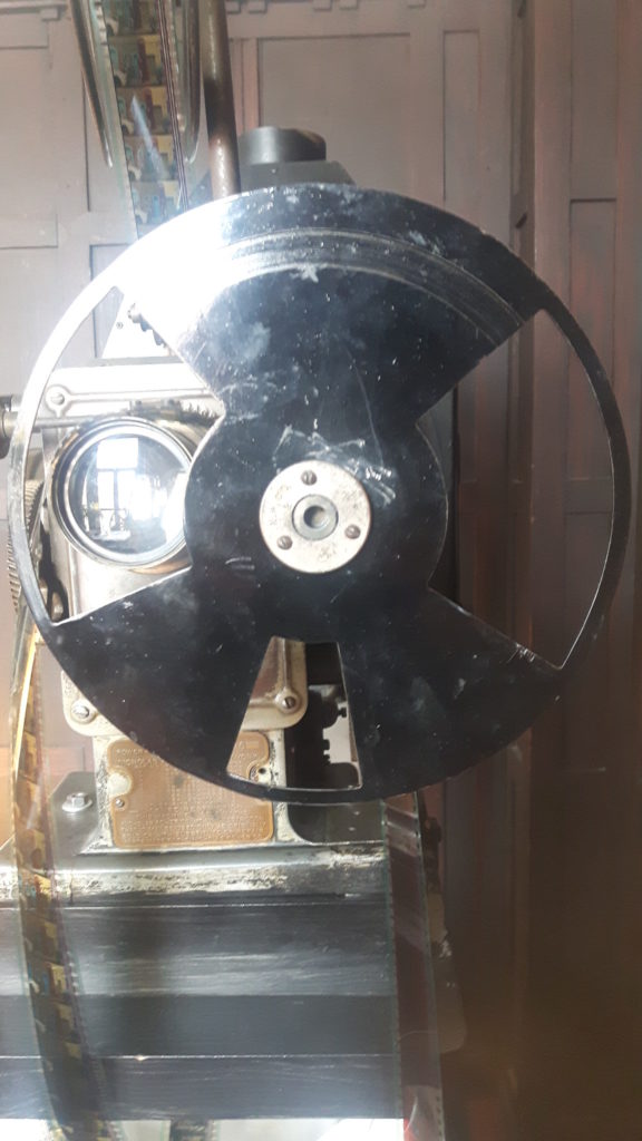
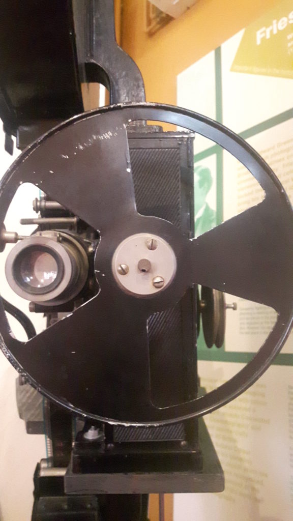
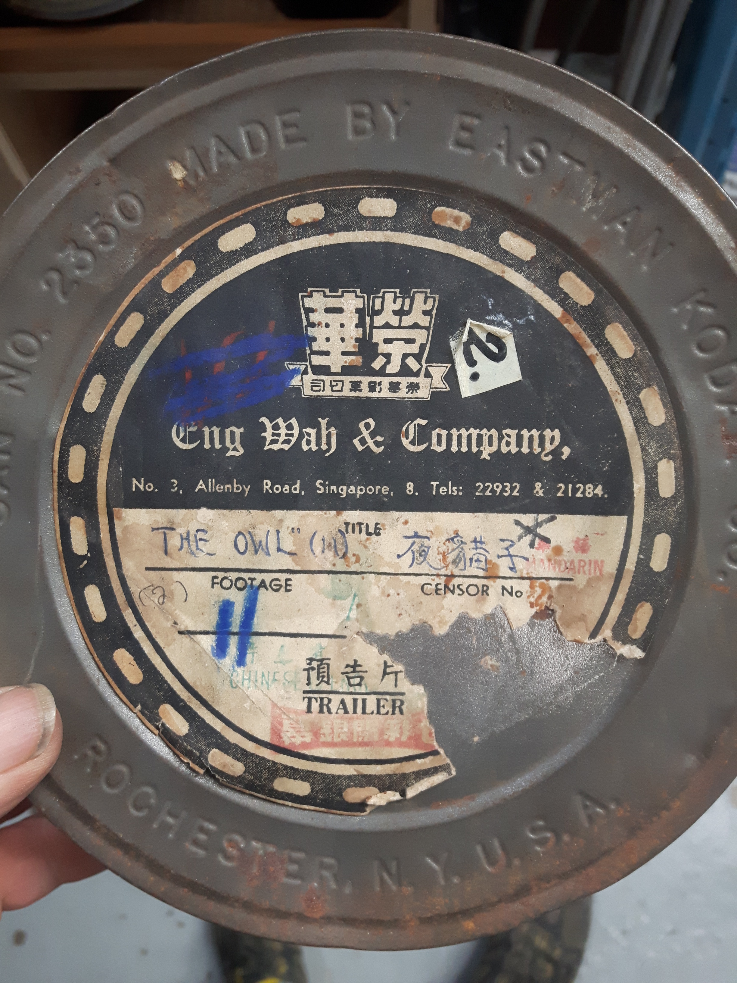
 Of course a important code is a object reference number and this will go in the Cat no’ line although it remains to be decided how these codes will be generated.